BT Prime Mover RR-30B Reach Truck Parts Manual – PDF DOWNLOAD
$28.95
BT Prime Mover RR-30B Reach Truck Parts Manual – PDF DOWNLOAD
Description
BT Prime Mover RR-30B Reach Truck Parts Manual – PDF DOWNLOAD
FILE DETAILS:
BT Prime Mover RR-30B Reach Truck Parts Manual – PDF DOWNLOAD
Language : English
Pages : 218
Downloadable : Yes
File Type : PDF
IMAGES PREVIEW OF THE MANUAL:
TABLE OF CONTENTS:
BT Prime Mover RR-30B Reach Truck Parts Manual – PDF DOWNLOAD
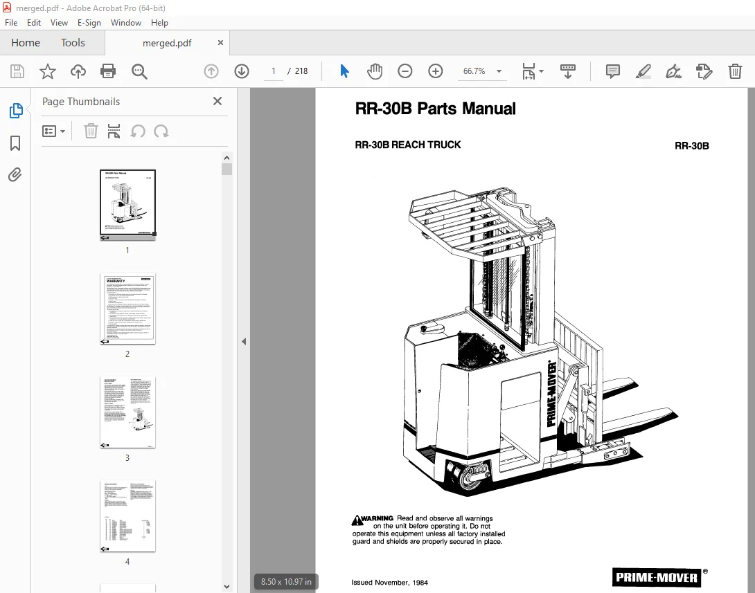
Front Cover 1
Warranty 2
Parts Ordering Instructions 3
General Information 4
Figure # 1 Parts List and Service Reference Index 6
Figure # 2 Decal and Part Assembly 8
Figure # 3 Shielding Assembly 9
Figure # 4 Emergency Disconnect Assembly 10
Figure # 5 Auxiliary Control Assembly 11
Figure # 6 Hand Lift and Speed Assembly 12
Figure # 7 Master Control Switch Assembly 14
Figure # 8 Steering Assembly 16
Figure # 9 Torque Generator Assembly 18
Figure # 10 Auxiliary Pump and Motor Assembly 19
Figure # 11 Auxiliary Pump Assembly 20
Figure # 12 Auxiliary Motor Assembly 21
Figure # 13 Transmission and Drive Motor Insulation 22
Figure # 14 Drive Motor and Brake Assembly 24
Figure # 15 Drive Motor Assembly 26
Figure # 16 Transmission Assembly 28
Figure # 17 Electrical Schematic 30
Figure # 18 Electrical Schematic Symbols 31
Figure # 19 Relay Wiring Harness Assembly 32
Figure # 20 Switch Relay Assembly 33
Figure # 21 Wiring Harness Assembly 34
Figure # 22 Wiring Assembly for Cold Storage 36
Figure # 23 2 Stage Mast Cable Assembly 37
Figure # 24 3 Stage Mast Cable Assembly 38
Figure # 25 Reach Cable Assembly 39
Figure # 26 Power Component Wiring 40
Figure # 27 SCR and Contactor Panel Assembly 41
Figure # 28 EV-1 SCR Control 42
Figure # 29 Transformer Assembly 43
Figure # 30 Rectifier Heat Sink Assembly 44
Figure # 31 G E Contactor Assembly 45
Figure # 32 G E Contactor Assembly 46
Figure # 33 Contactor Assembly 47
Figure # 34 Connector Assembly 48
Figure # 35 Warning Light Assembly 49
Figure # 36 Hydraulic Schematic 50
Figure # 37 Hydraulic Schematic Symbols 51
Figure # 38 Auxiliary Pump and Reservoir Assembly 52
Figure # 39 Hydraulic Reservoir Assembly 53
Figure # 40 Lift Pump and Motor Assembly 54
Figure # 41 Lift Pump and Motor Assembly 55
Figure # 42 Lift Motor Assembly 56
Figure # 43 24 Volt Lift Pump Assembly 57
Figure # 44 36 Volt Lift Pump Assembly 58
Figure # 45 Lift Control Valve Assembly 59
Figure # 46 Torque Generator and Filter Assembly 60
Figure # 47 Tube and Hose Assembly 61
Figure # 48 Auxiliary Control Valve Assembly 62
Figure # 49 2 Stage Cylinder and Reservoir Assembly 63
Figure # 50 2 Stage Cylinder Assembly 64
Figure # 51 3 Stage Cylinders and Reservoir Assembly 66
Figure # 52 3 Stage Staging Cylinder Assembly 68
Figure # 53 3 Stage Freelift Cylinder Assembly 69
Figure # 54 2 Stage Mast Hydraulic Hose Assembly 70
Figure # 55 3 Stage Mast Hydraulic Hose Assembly 71
Figure # 56 Standard Reach Hose Assembly 72
Figure # 57 Flow Divider Assembly 73
Figure # 59 Reach with Tilt Hose Assembly 74
Figure # 60 Reach with Tilt Manifold Valve Assembly 75
Figure # 61 Sideshifter Hose Assembly 76
Figure # 62 Sideshifter Cylinder Assembly 77
Figure # 63 Sideshifter Manifold Valve Assembly 78
Figure # 64 Deep Reach Valve and Hose Assembly 79
Figure # 65 Deep Reach Reach Cylinder and Hose Assembly 80
Figure # 66 Deep Reach Manifold Valve Assembly 81
Figure # 67 Deep Reach, Reach Cylinder Assembly 82
Figure # 68 Deep Reach, Tilt Cylinder and Hose Assembly 83
Figure # 69 Deep Reach, Tilt Cylinder Assembly 84
Figure # 71 2 Stage Mast Insulation Assembly 85
Figure # 72 2 Stage Inner Column Assembly 86
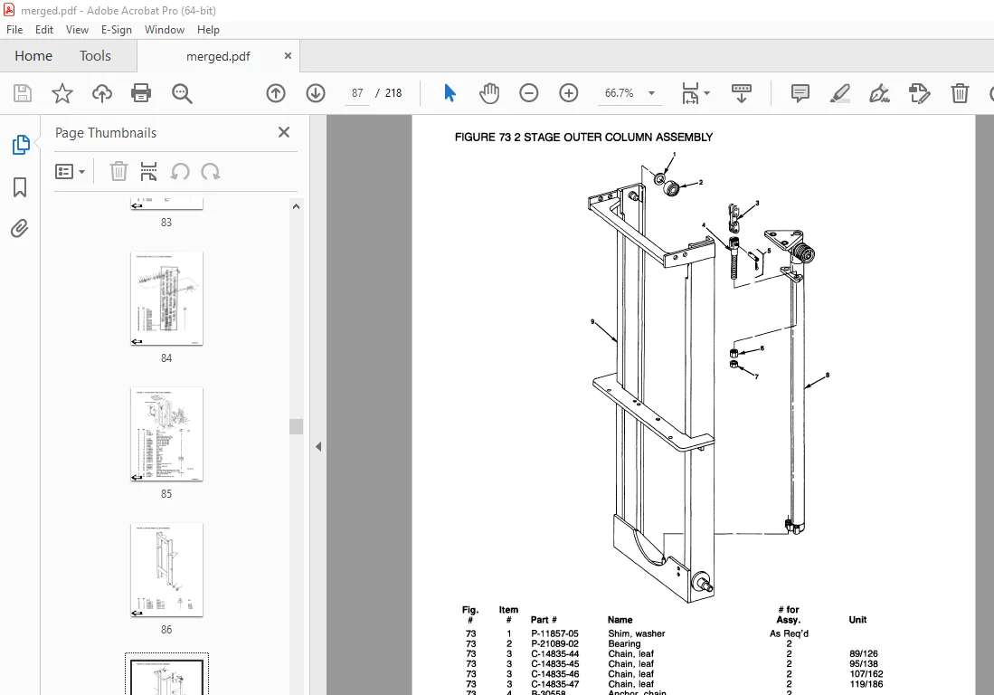
Figure # 73 2 Stage Outer Column Assembly 87
Figure # 74 2 Stage Cylinder Assembly and Related Parts 88
Figure # 75 Single Reach Assembly 89
Figure # 76 Single Reach Standard Front Frame Assembly 90
Figure # 77 Single Reach Tilt Front Frame Assembly 91
Figure # 78 Deep Reach Assembly 92
Figure # 79 Sideshifter Assembly 93
Figure # 80 Fork Assembly 94
Figure # 81 3 Stage Mast Insulation Assembly 95
Figure # 82 3 Stage Outer Column Assembly 96
Figure # 83 3 Stage Intermediate Column Assembly 97
Figure # 84 3 Stage Inner Column Assembly 98
Figure # 85 3 Stage Freelift Cylinder Assembly and Related Parts 99
Figure # 86 Main Frame and Load Wheel Assembly 100
Figure # 87 Caster Assembly 104
Figure # 88 Single Load Wheel Assembly 106
Figure # 89 4 Inch High Outriggers Articulating Load Wheel Assembly 107
Figure # 90 Articulating Load Wheel Assembly 108
Front Cover 109
Warranty 110
Parts Ordering Instructions 111
General Information 113
Figure 1 Parts List and Service Reference Index 114
Figure 2 Decal and Part Assembly 116
Figure 3 Shielding Assembly 117
Figure 4 Emergency Disconnect Assembly 118
Figure 5 Auxiliary Control Assembly 119
Figure 6 Hand Lift and Speed Assembly 120
Figure 7 Master Control Switch Assembly 122
Figure 8 Steering Assembly 124
Figure 9 Torque Generator Assembly 126
Figure 10 Auxiliary Pump and Motor Assembly 127
Figure 11 Auxiliary Pump Assembly 128
Figure 12 Auxiliary Motor Assembly 129
Figure 13 Transmission and Drive Motor Insulation 130
Figure 14 Drive Motor and Brake Assembly 132
Figure 15 Drive Motor Assembly 134
Figure 16 Transmission Assembly 136
Figure 17 Electrical Schematic 138
Figure 18 Electrical Schematic Symbols 139
Figure 21 Wiring Harness Assembly 142
Figure 22 Wiring Assembly for Cold Storage 144
Figure 23 2 Stage Mast Cable Assembly 145
Figure 24 3 Stage Mast Cable Assembly 146
Figure 25 Reach Cable Assembly 147
Figure 26 Power Component Wiring 148
Figure 27 SCR and Contactor Panel Assembly 149
Figure 28 EV-1 SCR Control 150
Figure 29 Transformer Assembly 151
Figure 30 Rectifier Heat Sink Assembly 152
Figure 31 GE Contactor Assembly 153
Figure 32 GE Contactor Assembly 154
Figure 33 Contactor Assembly 155
Figure 34 Connector Assembly 156
Figure 35 Warning Light Assembly 157
Figure 36 Hydraulic Schematic 158
Figure 37 Hydraulic Schematic Symbols 159
Figure 38 Auxiliary Pump and Reservoir Assembly 160
Figure 39 Hydraulic Reservoir Assembly 161
Figure 40 Lift Pump and Motor Assembly 162
Figure 41 Lift Pump and Motor Assembly 163
Figure 42 Lift Motor Assembly 164
Figure 43 24 Volt Lift Pump Assembly 165
Figure 44 36 Volt Lift Pump Assembly 166
Figure 45 Lift Control Valve Assembly 167
Figure 46 Torque Generator and Filter Assembly 168
Figure 47 Tube and Hose Assembly 169
Figure 48 Auxiliary Control Valve Assembly 170
Figure 49 2 Stage Cylinder and Reservoir Assembly 171
Figure 50 2 Stage Cylinder Assembly 172
Figure 51 3 Stage Cylinders and Reservoir Assembly 174
Figure 52 3 Stage Staging Cylinder Assembly 176
Figure 53 3 Stage Freelift Cylinder Assembly 177
Figure 54 2 Stage Mast Hydraulic Hose Assembly 178
Figure 55 3 Stage Mast Hydraulic Hose Assembly 179
Figure 56 Standard Reach Hose Assembly 180
Figure 57 Flow Divider Assembly 181
Figure 58 Reach and Tilt Cylinder Assembly 182
Figure 59 Reach with Tilt Hose Assembly 183
Figure 60 Reach with Tilt Manifold Valve Assembly 184
Figure 61 Sideshifter Hose Assembly 185
Figure 62 Sideshifter Cylinder Assembly 186
Figure 63 Sideshifter Manifold Valve Assembly 187
Figure 64 Deep Reach, Valve and Hose Assembly 188
Figure 65 Deep Reach, Reach Cylinder and Hose Assembly 189
Figure 66 Deep Reach, Manifold Valve Assembly 190
Figure 67 Deep Reach, Reach Cylinder Assembly 191
Figure 68 Deep Reach, Tilt Cylinder and Hose Assembly 192
Figure 69 Deep Reach, Tilt Cylinder Assembly 193
Figure 70 Deep Reach, Sideshifter Hose Assembly 194
Figure 71 2 Stage Mast Insulation Assembly 195
Figure 72 2 Stage Inner Column Assembly 196
Figure 73 2 Stage Outer Column Assembly 197
Figure 74 2 Stage Cylinder Assembly and Related Parts 198
Figure 75 Single Reach Assembly 199
Figure 76 Single Reach Standard Front Frame Assembly 200
Figure 77 Single Reach Tilt Front Frame Assembly 201
Figure 78 Deep Reach Assembly 202
Figure 79 Sideshifter Assembly 203
Figure 80 Fork Assembly 204
Figure 81 3 Stage Mast Insulation Assembly 205
Figure 82 3 Stage Outer Column Assembly 206
Figure 83 3 Stage Intermediate Column Assembly 207
Figure 84 3 Stage Inner Column Assembly 208
Figure 85 3 Stage Freelift Cylinder Assembly and Related Parts 209
Figure 86 Main Frame and Load Wheel Assembly 210
Figure 87 Caster Assembly 214
Figure 88 Single Load Wheel Assembly 216
Figure 89 4 Inch High Outriggers Articulating Load Wheel Assembly 217
Figure 90 Articulating Load Wheel Assembly 218
DESCRIPTION:
BT Prime Mover RR-30B Reach Truck Parts Manual – PDF DOWNLOAD
PARTS ORDERING INSTRUCTIONS:
HOW TO ORDER:
- When you order, supply the part number, quantity, model and serial numbers of your machine. Supplying this information will assure prompt, efficient handling of your order. The pictorial reference number is not needed and including it can only add confusion.
- Since your dealer carries many parts in stock and maintains up-to-date prices on all parts, he will be able to process your order immediately. If, for some reason, the part is not in stock, he will order it from the factory. In either event, he maintains a current file of service manuals, which give all available parts ordering or technical information.
- All prices are FOB factory in Muscatine, Iowa. Shipping charges are added to the price of the part shipping from the factory.
WHERE TO ORDER
Always order parts from the dealer who sold you your Prime Mover. If it is necessary for the dealer to order parts from the factory, he is able to get prompt service for you. Parts are shipped in accordance with shipping instructions given on the order.
S.V 20/01/2025