BT-Prime Mover RMX HMX Electric Low Lift Pallet Truck Service Manual PDF
$28.95
BT-Prime Mover RMX HMX Electric Low Lift Pallet Truck Service Manual – PDF DOWNLOAD
Part no: 313701-000
Effective Serial Number MX__241341-UP
Description
BT-Prime Mover RMX HMX Electric Low Lift Pallet Truck Service Manual – PDF DOWNLOAD
FILE DETAILS:
BT-Prime Mover RMX HMX Electric Low Lift Pallet Truck Service Manual – PDF DOWNLOAD
Language : English
Pages : 462
Downloadable : Yes
File Type : PDF
IMAGES PREVIEW OF THE MANUAL:
TABLE OF CONTENTS:
BT-Prime Mover RMX HMX Electric Low Lift Pallet Truck Service Manual – PDF DOWNLOAD
Part no: 313701-000
Effective Serial Number MX__241341-UP
Front Cover 1
Standard Codes 3
Table of Contents 5
Warning Symbols 15
1 Warning Levels 15
Prohibitory Symbols 16
1 Ordinance Symbols 16
Safety 17
1 General Safety 17
Battery Safety 21
Static Discharge Precautions 26
Welding Safety 28
Introduction, Service Manual 31
Contents, Section M 33
1 Machine Information 33
General Product Information 35
1 Truck Presentation 35
1 1 Truck Side Views 36
1 2 Intended Truck Application 36
1 3 Prohibited Truck Application 36
1 4 Truck Data 37
1 5 Truck Dimensions 38
1 6 Data Plate 41
2 Main Components 44
Inch (SAE) and Metric Fasteners 47
1 Introduction 47
2 Nomenclature, Threads 48
3 Strength Identification 49
4 Conversion of Metric and English Units 56
Technical Service Data 59
Ordering Spare Parts 63
Contents, Section P 65
1 Planned Maintenance 65
Introduction, Maintenance 67
1 Jacking Truck Off The Floor 68
1 1 Elevate Rear of Truck 68
1 1 Elevate Either Side of Truck 68
2 Lubricants 68
2 1 Standard 68
2 2 Cold Storage 69
Service Schedule 71
1 Planned Maintenance Schedule 71
2 Planned Maintenance Procedures 75
2 1 Services Performed Daily or Every 8 Operating Hours 75
2 1 1 Battery Discharge Indicator With Lift Cut Out (Optional) 75
2 1 2 Functions/Operations 75
2 1 3 Hourmeter 76
2 1 4 Hydraulic System 76
2 1 5 Frame/Sheet Metal 76
2 1 6 Wheels/Tires 76
2 1 7 Brakes 76
2 2 Services Performed Weekly or Every 30 Operating Hours 76
2 2 1 Battery 76
2 3 Services Performed Monthly or Every 120 Operating Hours 77
2 3 1 Inspection 77
2 3 2 Transmission 77
2 3 3 Brake 77
2 3 4 Battery 77
2 3 5 Motors 78
2 3 6 Hydraulic Reservoir 78
2 3 7 Frame Lube 78
2 3 8 Pivot Points 78
2 4 Services Performed Quarterly or Every 360 Operating Hours 79
2 4 1 Wheels/Tires 79
2 4 2 Hydraulic System 79
2 4 3 Pivot Points 79
2 5 Services Performed Semi-Annually or Every 720 Operating Hours 79
2 5 1 Frame 79
2 5 2 Drive Gear 79
2 5 3 Brakes 80
2 5 4 Steering Control Handle 80
2 5 5 Instrument Panel 80
2 5 6 Electrical Control System 80
2 5 7 Electrical Panel 80
2 5 8 Electrical Connections 80
2 5 9 Contactor Tips (NOT Sealed) 80
2 5 10 Hydraulic System 80
2 6 Services Performed Annually or Every 1440 Operating Hours 81
2 6 1 Inspection 81
2 6 2 Transmission 81
2 6 3 Battery 81
2 6 4 Hydraulic System 82
2 6 5 Brakes 82
Lubrication Chart 83
Oil and Grease Specifications 84
1 Approved Oils and Grease 84
2 Grease Location Points 85
Contents, Section S 87
1 Service Instructions 87
Frame 89
1 Theory of Operation 91
2 Maintenance 91
2 1 Inspection 91
3 Troubleshooting 91
4 Repair and Rebuild 92
4 1 Installation 93
Inspection Covers 95
1 Theory of Operation 96
2 Maintenance 96
3 Troubleshooting 96
4 Repair and Rebuild 96
Battery Compartment 97
1 Theory of Operation 98
2 Maintenance 98
3 Troubleshooting 98
4 Repair and Rebuild 99
4 1 Battery Door 99
4 2 Battery Rollers 100
Operator Controls 101
1 Theory of Operation 103
2 Maintenance 103
3 Troubleshooting 103
4 Repair and Rebuild 103
4 1 Control Handle 103
4 2 Handle Rail 104
Decals 107
1 Decal with Protective Sheet 107
2 Decal without Protective Sheet 107
Electric Motors 109
1 Theory of Operation 109
2 Maintenance 109
2 1 Commutator 110
2 2 Motor Brush Inspection 111
3 Troubleshooting 113
4 Repair 121
4 1 Brush Replacement 121
4 2 Pump Motor 122
4 3 Drive Motor 129
5 Rebuild 131
5 1 Pump Motor and Drive Motor Component Disassembly 131
5 2 Inspection 133
5 2 1 Drive End Head 133
5 2 2 Commutator End Head 133
5 2 3 Bearings 133
5 2 4 Armature 133
5 2 5 Frame and Field Assembly 134
5 3 Assembly/Testing 135
5 3 1 Bearing Installation 135
5 3 2 Testing 136
Transmission 137
1 Theory of Operation 138
2 Maintenance 138
2 1 Fluid Changing 138
3 Troubleshooting 139
4 Repair and Rebuild 140
4 1 Transmission Disassembly 140
4 1 Axle Seal 145
Parking Brake System 147
1 Theory of Operation 148
2 Maintenance 148
2 1 Brake Adjustment 148
3 Troubleshooting 149
4 Repair and Rebuild 149
4 1 Brake Shoe 149
Drive Wheel 151
1 Theory of Operation 151
2 Maintenance 151
3 Troubleshooting 151
4 Repair and Rebuild 152
Support / Swivel Wheels 155
1 Theory of Operation 156
2 Maintenance 156
2 1 Inspection 156
3 Troubleshooting 157
4 Repair and Rebuild 157
Load Wheels 159
1 Theory of Operation 161
2 Maintenance 161
3 Troubleshooting 161
4 Repair and Rebuild 161
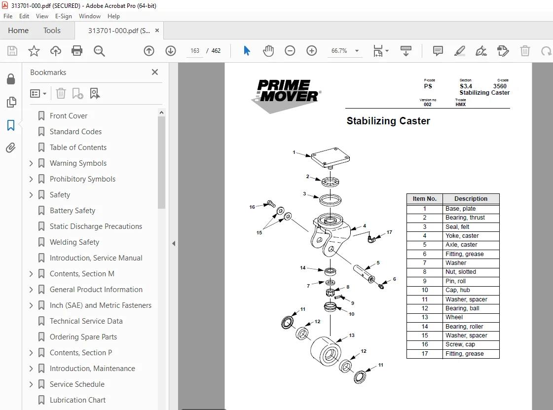
Stabilizing Caster 163
1 Theory of Operation 164
2 Maintenance 164
2 1 Inspection 164
3 Troubleshooting 164
4 Repair and Rebuild 165
Stabilizing Caster Spring Loaded 167
1 Theory of Operation 168
2 Maintenance 168
2 1 Inspection 168
3 Troubleshooting 168
4 Repair and Rebuild 169
Steering Arm / Wheel (Tiller Arm) 173
1 Theory of Operation 177
2 Maintenance 177
2 1 Inspection 177
3 Troubleshooting 177
4 Repair and Rebuild 178
Steering Arm/Wheel (Head) 181
1 Theory of Operation 183
2 Maintenance 183
3 Troubleshooting 183
4 Repair and Rebuild 183
Steering Bearing 185
1 Theory of Operation 186
2 Maintenance 186
3 Troubleshooting 186
4 Repair and Rebuild 187
Electrical Functions, 12 Volt 189
1 Theory of Operation 190
1 1 Battery Connected/Master Control On/ Off Switch in “On” Position 190
1 2 Key Switch in “ON” Position 190
1 3 Control Handle Down/Brakes Released/Brake Interlock Switch Closed 191
1 4 Travel, Forks-first Direction 191
1 5 Travel, Forks-trailing Direction 192
1 6 Transistor Controller Power Circuits 192
1 7 Accelerator Potentiometer Circuits 193
1 8 Reverser Switch 193
1 9 Forks Lifting 194
1 10 Forks Lowering 195
2 Maintenance 200
2 1 Wiring 200
2 1 1 Definitions 200
3 Troubleshooting 201
Electrical Functions, 24 Volt 300 Amp 221
1 Theory of Operation 222
1 1 Start-up A 222
1 2 Start-up B 224
1 3 Travel, Forks-trailing Direction 226
1 4 Travel, Forks-first Direction 227
1 5 Reverse 228
2 Maintenance 243
2 1 Wiring 243
2 1 1 Definitions 244
2 1 2 Shorts to Frame Test 245
3 Troubleshooting 249
Electrical Functions, 24 Volt 400 Amp 261
1 Theory of Operation 263
1 1 Start-up, A 264
1 2 Start-up B 266
1 3 Travel, Forks-trailing Direction 268
1 4 Travel, Forks-first Direction 269
1 5 High Speed 270
1 6 Reverse 271
2 Maintenance 291
2 1 Wiring 292
2 1 1 Definitions 292
2 1 2 Shorts to Frame Test 292
3 Troubleshooting 293
Battery 307
1 Theory of Operation 307
2 Maintenance 307
2 1 Inspection and Care 307
2 2 Exterior Cleaning 308
2 3 Charging 308
2 4 Storage 309
2 5 History Record 309
3 Troubleshooting 310
4 Repair and Rebuild 311
Battery Connector 313
1 Theory of Operation 313
2 Maintenance 313
2 1 Inspection 313
3 Troubleshooting 314
4 Repair and Rebuild 314
Horn 317
1 Theory of Operation 318
2 Maintenance 318
3 Troubleshooting 318
4 Repair and Rebuild 318
Line Contactor 321
1 Theory of Operation 323
2 Maintenance 323
3 Troubleshooting 323
4 Repair and Rebuild 324
Battery Controller/Hourmeter/Lift Interrupt 327
1 Theory of Operation 327
2 Maintenance 329
2 1 Discharge Adjustment 329
3 Troubleshooting 331
3 1 Battery Discharge Indicator (BDI) 331
3 2 Hourmeter 333
Battery Discharge Indicator/ Hourmeter 335
1 Theory of Operation 335
2 Maintenance 337
3 Troubleshooting 337
3 1 Battery Discharge Indicator (BDI) 337
3 2 Hourmeter 339
Switches 341
1 Theory of Operation 343
2 Maintenance 343
2 1 Key Switch Inspection 343
2 2 Master Control On/Off Switch Inspection 343
2 3 Lift Limit Switch Adjustment 344
2 4 Magnetic (Reed) Switch Adjustment 345
2 5 Brake Interlock Switch Adjustment 346
3 Troubleshooting 346
4 Repair and Rebuild 347
4 1 Key Switch 347
4 2 Master Control On/Off Switch 348
4 3 Lift Limit Switch 349
4 4 Magnetic (Reed) Switch 350
4 5 Brake Interlock Switch 351
Speed Controls 353
1 Theory of Operation 355
2 Maintenance 355
2 1 Potentiometer Adjustment 355
3 Troubleshooting 356
4 Repair and Rebuild 357
4 1 Potentiometer Assembly 357
4 2 Rearward and Forward Switches 359
Direction Contactors 361
1 Theory of Operation 362
2 Maintenance 362
2 1 Resistance Testing 362
2 2 Contact Tip Inspection 362
2 3 Parts Inspection 363
3 Troubleshooting 363
4 Repair and Rebuild 363
1A Speed Contactor 369
1 Theory of Operation 370
2 Maintenance 370
2 1 Resistance Testing 370
2 2 Contact Tip Inspection 370
2 3 Parts Inspection 370
3 Troubleshooting 370
4 Repair and Rebuild 371
12 Volt Transistor Controller 375
1 Theory of Operation 375
1 1 Basics Of Circuit Operation 375
2 Maintenance 376
2 1 Safety 376
2 2 Cleaning 376
2 3 Controller Adjustments 377
2 4 Definitions 377
3 Troubleshooting 378
4 Repair and Rebuild 380
24 Volt, 300 Amp Transistor Controller 381
1 Theory of Operation 381
1 1 Basics Of Circuit Operation 381
1 2 Control Features 383
1 3 Motor Circuit 384
1 4 Control Circuit 385
2 Maintenance 386
2 1 Safety 386
2 2 Cleaning 386
2 3 Transistor Adjustable Settings 387
2 4 Definitions 388
3 Troubleshooting 388
3 1 Diagnostics and Troubleshooting 388
3 2 Handset Diagnostics 389
3 3 Troubleshooting Chart 391
3 4 Troubleshooting Chart Using Handset 393
4 Repair and Rebuild 394
24 Volt, 400 Amp Transistor Controller 395
1 Theory of Operation 395
1 1 Basics Of Circuit Operation 395
1 2 Control Features 397
1 3 Motor Circuit 398
1 4 Control Circuit 399
2 Maintenance 401
2 1 Safety 401
2 2 Cleaning 401
2 3 Transistor Adjustable Settings 402
2 4 Definitions 403
3 Troubleshooting 404
3 1 Diagnostics and Troubleshooting 404
3 2 Handset Diagnostics 404
3 3 Troubleshooting Chart 407
3 4 Troubleshooting Chart Using Handset 410
4 Repair and Rebuild 411
Hydraulic System 413
1 Theory of Operation 413
1 1 Electric Lift 413
1 2 Electric Lower 414
1 3 Hydraulic Lift 416
1 4 Hydraulic Relief 417
1 5 Hydraulic Hold 418
1 6 Hydraulic Lower 419
1 7 Relief Pressure 420
2 Maintenance 420
2 1 Hydraulic Fluid Check 420
2 2 Adjustments 420
3 Troubleshooting 422
4 Repair and Rebuild 430
Lift Cylinder 437
1 Theory of Operation 438
2 Maintenance 438
2 1 Inspection 438
3 Troubleshooting 438
4 Repair and Rebuild 439
Handset, Old 443
1 Theory of Operation 443
Handset, New 451
1 Theory of Operation 451
Index 459
A 459
B 459
C 459
D 459
E 459
F 459
G 459
H 459
I 459
J 459
L 459
M 460
O 460
P 460
S 460
T 460
W 460
Back Cover 462
DESCRIPTION:
BT-Prime Mover RMX HMX Electric Low Lift Pallet Truck Service Manual – PDF DOWNLOAD
Part no: 313701-000
Effective Serial Number MX__241341-UP
Introduction, Service Manual:
- The information in this service manual covers models RMX and HMX.
Federal and State laws require that operators be completely trained in the safe operation of the trucks in accordance with OSHA regulation 1910.178. - An operator’s manual is sent with every Prime-Mover lift truck when it is manufactured.
- The information contained in this service manual is intended as a guide to help trained, qualified, and authorized technicians safely service the truck.
- The service manual is divided into four separate sections which cover needed information for servicing the truck types.
General Product Information:
1. Truck Presentation:
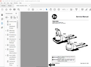
The RMX is a battery powered walkie pallet truck. The HMX is a battery powered riding pallet truck. The trucks are intended solely to be operated indoors carrying pallets or similar load carriers. The trucks are equipped with a steering arm with all the controls for operating within easy access. The trucks lifting capacity can be found on the truck’s data plate.
RMX trucks are equipped with a 12 Volt or 24 volt electrical system. HMX trucks are equipped with a 24 volt electrical system. Speed is regulated by means of a transistor controller to provide infinite control of acceleration and speed while driving.
- The forks are raised by means of a hydraulic unit. Control of the lift/lower is done electrically with separate push buttons on the control handle. HMX trucks have additional controls for raising and lowering located on the rider control bar and can be operated with either hand.
- Trucks can be fitted with different accessories including an hourmeter/battery discharge indicator, and hourmeter/battery discharge indicator with lift cutout, and a package guard on the backrest. The truck can also be fitted with plated axles and low temperature oil for use in cool and humid conditions.
S.V 11/01/2025