BT Prime-Mover RMX HMX Electric Low Lift Pallet Truck Part Manual PDF
$33.95
BT Prime-Mover RMX HMX Electric Low Lift Pallet Truck Part Manual – PDF DOWNLOAD
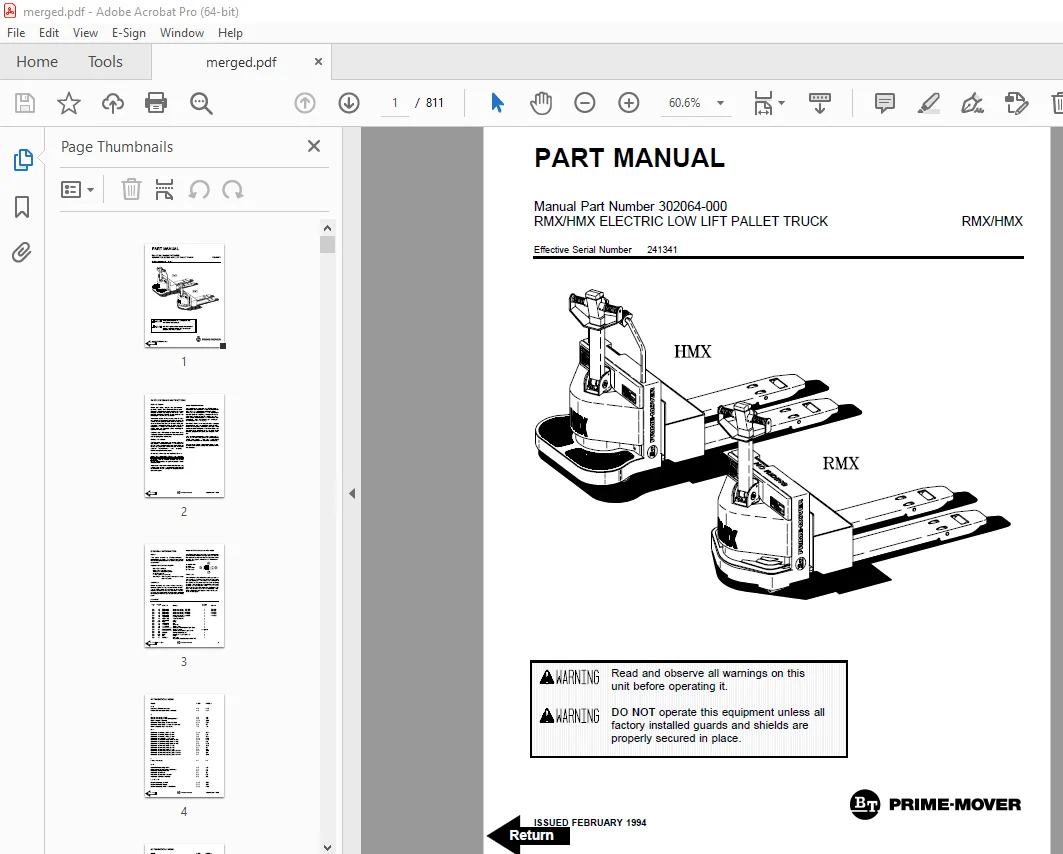
Manual Part Number 302064-000
Effective Serial Number 241341
Description
BT Prime-Mover RMX HMX Electric Low Lift Pallet Truck Part Manual – PDF DOWNLOAD
FILE DETAILS:
BT Prime-Mover RMX HMX Electric Low Lift Pallet Truck Part Manual – PDF DOWNLOAD
Language : English
Pages : 811
Downloadable : Yes
File Type : PDF
IMAGES PREVIEW OF THE MANUAL:
TABLE OF CONTENTS:
BT Prime-Mover RMX HMX Electric Low Lift Pallet Truck Part Manual – PDF DOWNLOAD
Manual Part Number 302064-000
Effective Serial Number 241341
Front Cover 1
Parts Ordering Instructions 2
General Information 3
Alphabetical Index 4
Section 0 0 6
Figure # 0 1 6
Section 1 0 8
Figure # 1 1 8
Figure # 1 2 10
Figure # 1 3 12
Section 2 0 14
Figure # 2 1 14
Figure # 2 2 15
Figure # 2 3 16
Figure # 2 4 18
Figure # 2 5 20
Figure # 2 6 22
Figure # 2 7 23
Figure # 2 8 24
Figure # 2 9 26
Figure # 2 10 28
Figure # 2 11 29
Figure # 2 12 30
Figure # 2 13 32
Figure # 2 14 34
Figure # 2 15 36
Figure # 2 16 38
Figure # 2 17 40
Figure # 2 18 42
Figure # 2 19 44
Figure # 2 20 46
Section 3 0 48
Figure # 3 1 48
Figure # 3 2 49
Figure # 3 3 50
Figure # 3 4 52
Section 4 0 54
Figure # 4 1 54
Figure # 4 2 56
Figure # 4 3 58
Figure # 4 4 60
Figure # 4 5 62
Figure # 4 6 64
Figure # 4 7 66
Figure # 4 8 68
Figure # 4 9 70
Section 10 0 72
Figure # 10 1 72
Numberical Index 75
Back Cover 84
Front Cover 85
Parts Ordering Instructions 86
General Information 87
Alphabetical Index 88
Section 0 0 90
Figure # 0 1 90
Section 1 0 92
Figure # 1 1 92
Figure # 1 2 94
Figure # 1 3 96
Section 2 0 98
Figure # 2 1 98
Figure # 2 2 99
Figure # 2 3 100
Figure # 2 4 102
Figure # 2 5 104
Figure # 2 6 106
Figure # 2 7 107
Figure # 2 8 108
Figure # 2 9 110
Figure # 2 10 112
Figure # 2 11 113
Figure # 2 12 114
Figure # 2 13 116
Figure # 2 14 118
Figure # 2 15 120
Figure # 2 16 122
Figure # 2 17 124
Figure # 2 18 126
Figure # 2 19 128
Figure # 2 20 130
Section 3 0 132
Figure # 3 1 132
Figure # 3 2 133
Figure # 3 3 134
Figure # 3 4 136
Section 4 0 138
Figure # 4 1 138
Figure # 4 2 140
Figure # 4 3 142
Figure # 4 4 144
Figure # 4 5 146
Figure # 4 6 148
Figure # 4 7 150
Figure # 4 8 152
Figure # 4 9 154
Section 10 0 156
Figure # 10 1 156
Back Cover 158
Front Cover 159
Parts Ordering Instructions 160
General Information 161
Alphabetical Index 162
Section 0 0 164
Figure # 0 1 Decals and Parts List Assembly 164
Section 1 0 166
Figure # 1 1 Handle and Transmission Installation 166
Figure # 1 2 Control Handle Head Assembly 168
Figure # 1 3 Transmission Assembly 170
Section 2 0 172
Figure # 2 1 RMX 12 Volt Electrical Schematic 172
Figure # 2 2 RMX 12 Volt Electrical Schematic Symbols 173
Figure # 2 3 RMX 12 Volt Electrical Assembly 174
Figure # 2 4 RMX 12 Volt Electrical Panel Assembly 176
Figure # 2 5 12 & 24 Volt Forward & Rearward Contactor Assembly 178
Figure # 2 6 RMX 24 Volt Electrical Schematic 180
Figure # 2 7 RMX 24 Volt Electrical Schematic Symbols 181
Figure # 2 8 RMX 24 Volt Electrical Assembly 182
Figure # 2 9 RMX 24 Volt Electrical Panel Assembly 184
Figure # 2 10 HMX 24 Volt Electrical Schematic 186
Figure # 2 11 HMX 24 Volt Electrical Schematic Symbols 187
Figure # 2 12 HMX 24 Volt Electrical Assembly 188
Figure # 2 13 HMX 24 Volt Electrical Panel Assembly 190
Figure # 2 14 HMX 24 Volt 1A Contactor Assembly 192
Figure # 2 15 12/24 Volt Electrical Lift Interrupt 194
Figure # 2 16 Cold Storage Assembly 196
Figure # 2 17 Pump Motor Assembly 198
Figure # 2 18 RMX 12 Volt Drive Motor Assembly 200
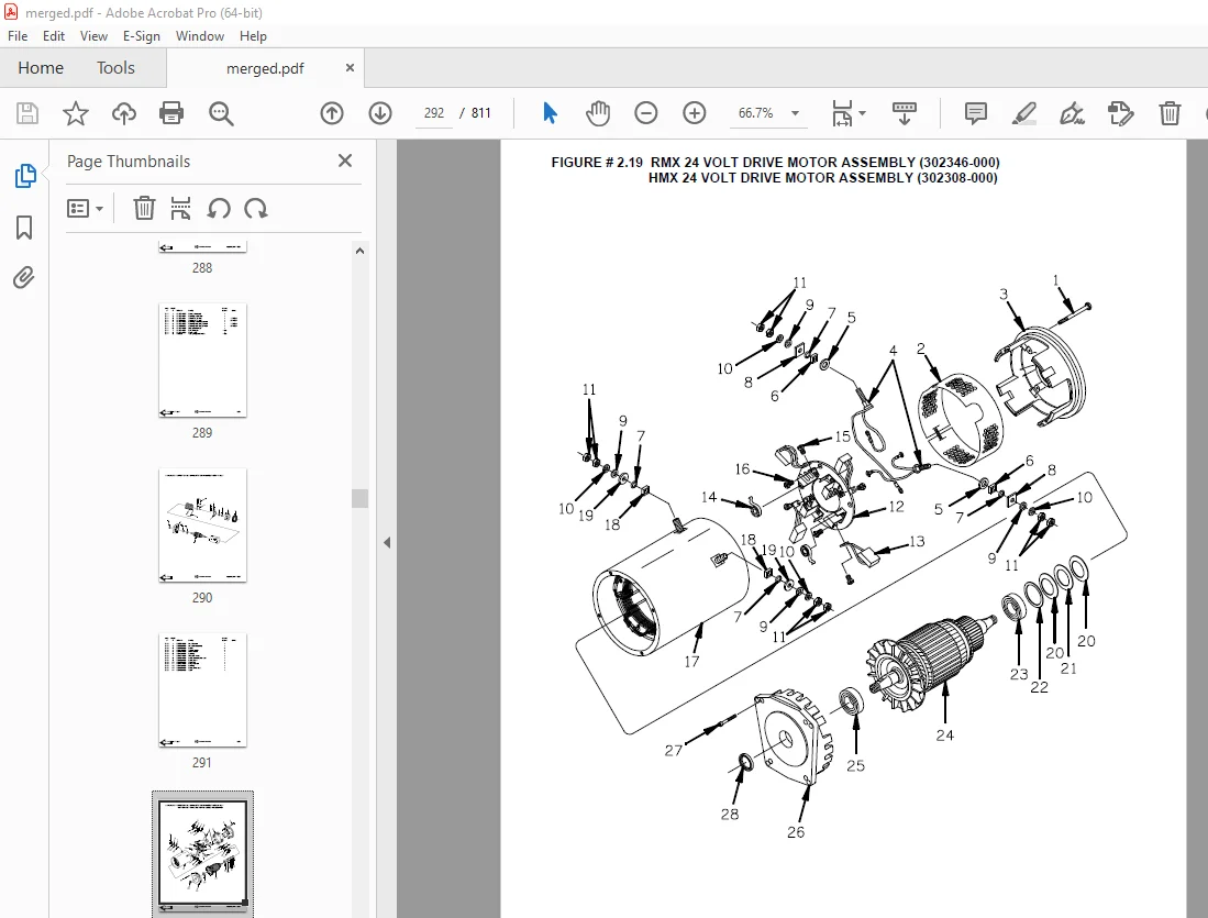
Figure # 2 19 RMX/HMX 24 Volt Drive Motor Assembly 202
Figure # 2 20 HMX 24 Volt Drive Motor Assembly 204
Section 3 0 206
Figure # 3 1 Hydraulic Schematic 206
Figure # 3 2 Hydraulic Schematic Symbols 207
Figure # 3 3 Hydraulic System Assembly 208
Figure # 3 4 Hydraulic Pump and Motor 210
Section 4 0 212
Figure # 4 1 Frame Assembly 212
Figure # 4 2 RMX Spring Loaded Caster Assembly 216
Figure # 4 3 Load Wheel Assembly 218
Figure # 4 4 HMX Hand Rail Assembly 220
Figure # 4 5 HMX Caster Torsion Rod Assembly 222
Figure # 4 6 HMX Caster Assembly 224
Figure # 4 7 Battery Rollers and Frame Assembly 226
Figure # 4 8 Pallet Entry Rollers 228
Figure # 4 9 Removable Load Backrest 230
Figure # 4 10 Shields and Guards 232
Section 10 0 234
Figure # 10 1 Special Tools and Lubrications 234
Numerical Index 237
Back Cover 246
Front Cover 247
Parts Ordering Instructions 248
General Information 249
Alphabetical Index 250
Section 0 0 252
Figure # 0 1 252
Section 1 0 254
Figure # 1 1 254
Figure # 1 2 256
Figure # 1 3 258
Figure # 1 4 260
Section 2 0 262
Figure # 2 1 262
Figure # 2 2 263
Figure # 2 3 264
Figure # 2 4 266
Figure # 2 5 268
Figure # 2 6 270
Figure # 2 7 271
Figure # 2 8 272
Figure # 2 9 274
Figure # 2 10 276
Figure # 2 11 277
Figure # 2 12 278
Figure # 2 13 280
Figure # 2 14 282
Figure # 2 15 284
Figure # 2 16 286
Figure # 2 17 288
Figure # 2 18 290
Figure # 2 19 292
Section 3 0 294
Figure # 3 1 294
Figure # 3 2 295
Figure # 3 3 296
Figure # 3 4 298
Section 4 0 300
Figure # 4 1 300
Figure # 4 2 304
Figure # 4 3 306
Figure # 4 4 308
Figure # 4 5 310
Figure # 4 6 312
Figure # 4 7 314
Figure # 4 8 316
Figure # 4 9 318
Figure # 4 10 320
Figure # 4 11 322
Section 10 0 324
Figure # 10 1 324
Numerical Index 327
Back Cover 336
Front Cover 337
Parts Ordering Instructions 338
General Information 339
Alphabetical Index 340
Section 0 0 342
Figure # 0 1 Decals and Parts List Assembly 342
Section 1 0 344
Figure # 1 1 Handle and Transmission Installation 344
Figure # 1 2 Control Handle Head Assembly 346
Figure # 1 3 Walk Along Knob Control Handle Head Assembly 348
Figure # 1 4 Transmission Assembly 350
Section 2 0 352
Figure # 2 1 RMX 12 Volt Electrical Schematic 352
Figure # 2 2 RMX 12 Volt Electrical Schematic Symbols 353
Figure # 2 3 RMX 12 Volt Electrical Assembly 354
Figure # 2 4 RMX 12 Volt Electrical Panel Assembly 356
Figure # 2 5 12 & 24 Volt Forward & Rearward Contactor Assembly 358
Figure # 2 6 RMX 24 Volt Electrical Schematic 360
Figure # 2 7 RMX 24 Volt Electrical Schematic Symbols 361
Figure # 2 8 RMX 24 Volt Electrical Assembly 362
Figure # 2 9 RMX 24 Volt Electrical Panel Assembly 364
Figure # 2 10 HMX 24 Volt Electrical Schematic 366
Figure # 2 11 HMX 24 Volt Electrical Schematic Symbols 367
Figure # 2 12 HMX 24 Volt Electrical Assembly 368
Figure # 2 13 HMX 24 Volt Electrical Panel Assembly 370
Figure # 2 14 HMX 24 Volt 1A Contactor Assembly 372
Figure # 2 15 12/24 Volt Electrical Lift Interrupt 374
Figure # 2 16 Cold Storage Assembly 376
Figure # 2 17 Pump Motor Assembly 378
Figure # 2 18 RMX 12 Volt Drive Motor Assembly 380
Figure # 2 19 RMX/HMX 24 Volt Drive Motor Assembly 382
Section 3 0 384
Figure # 3 1 Lift Hydraulic Schematic 384
Figure # 3 2 Hydraulic Schematic Symbols 385
Figure # 3 3 Hydraulic System Assembly 386
Figure # 3 4 Hydraulic Pump and Motor Assembly 388
Section 4 0 390
Figure # 4 1 Frame Assembly 390
Figure # 4 2 RMX Spring Loaded Caster Assembly 394
Figure # 4 3 Load Wheel Assembly 396
Figure # 4 4 HMX Hand Rail Assembly 398
Figure # 4 5 HMX Caster Torsion Rod Assembly 400
Figure # 4 6 HMX Caster Assembly 402
Figure # 4 7 Battery Rollers and Frame Assembly 404
Figure # 4 8 Pallet Entry Rollers 406
Figure # 4 9 Removable Load Backrest 408
Figure # 4 10 Shields and Guards 410
Figure # 4 11 Tilting Package Guard Assembly 412
Section 10 0 414
Figure # 10 1 Special Tools and Lubrications 414
Numerical Index 417
Back Cover 426
Front Cover 427
Parts Ordering Instructions 428
General Information 429
Alphabetical Index 430
Section 0 0 432
Figure # 0 1 Decals and Parts List Assembly 432
Section 1 0 434
Figure # 1 1 Handle and Transmission Installation 434
Figure # 1 2 Control Handle Head Assembly 436
Figure # 1 3 Walk Along Knob Control Handle Head Assembly 438
Figure # 1 4 Transmission Assembly 440
Figure # 1 5 Drive Wheel Assembly 442
Section 2 0 444
Figure # 2 1 RMX 12 Volt Electrical Schematic 444
Figure # 2 2 RMX 12 Volt Electrical Schematic Symbols 445
Figure # 2 3 RMX 12 Volt Electrical Assembly 446
Figure # 2 4 RMX 12 Volt Electrical Panel Assembly 448
Figure # 2 5 Forward & Rearward Contactor Assembly 450
Figure # 2 6 RMX 24 Volt Electrical Schematic 452
Figure # 2 7 RMX 24 Volt Electrical Schematic Symbols 453
Figure # 2 8 RMX 24 Volt Electrical Assembly 454
Figure # 2 9 RMX 24 Volt Electrical Panel Assembly 456
Figure # 2 10 HMX 24 Volt Electrical Schematic 458
Figure # 2 11 HMX 24 Volt Electrical Schematic Symbols 459
Figure # 2 12 HMX 24 Volt Electrical Assembly 460
Figure # 2 13 HMX 24 Volt Electrical Panel Assembly 462
Figure # 2 14 HMX 24 Volt 1A Contactor Assembly 464
Figure # 2 15 12/24 Volt Electrical Lift Interrupt 466
Figure # 2 16 Cold Storage Assembly 468
Figure # 2 17 Pump Motor Assembly 470
Figure # 2 18 RMX 12 Volt Drive Motor Assembly 472
Figure # 2 19 RMX/HMX 24 Volt Drive Motor Assembly 474
Figure # 2 20 Power Connector Assembly 476
Section 3 0 478
Figure # 3 1 Lift Hydraulic Schematic 478
Figure # 3 2 Hydraulic Schematic Symbols 479
Figure # 3 3 Hydraulic System Assembly 480
Figure # 3 4 Hydraulic Pump and Motor Assembly 482
Section 4 0 484
Figure # 4 1 Frame Assembly 484
Figure # 4 2 RMX Spring Loaded Caster Assembly 488
Figure # 4 3 Load Wheel Assembly 490
Figure # 4 4 HMX Hand Rail Assembly 492
Figure # 4 5 HMX Caster Torsion Rod Assembly 494
Figure # 4 6 HMX Caster Assembly 496
Figure # 4 7 Battery Rollers and Frame Assembly 498
Figure # 4 8 Pallet Entry Rollers 500
Figure # 4 9 Removable Load Backrest 502
Figure # 4 10 Shields and Guards 504
Figure # 4 11 Tilting Package Guard Assembly 506
Section 10 0 508
Figure # 10 1 Special Tools and Lubrications 508
Numerical Index 511
Back Cover 521
Front Cover 522
Parts Ordering Instructions 523
General Information 524
Alphabetical Index 525
Section 0 0 527
Figure # 0 1 Decals and Parts List Assembly 527
Section 1 0 529
Figure # 1 1 Handle and Transmission Installation 529
Figure # 1 2 Control Handle Head Assembly 531
Figure # 1 3 Walk Along Knob Control Handle Head Assembly 533
Figure # 1 4 Transmission Assembly 535
Figure # 1 5 Drive Wheel Assembly 537
Section 2 0 539
Figure # 2 1 RMX 12 Volt Electrical Schematic 539
Figure # 2 2 RMX 12 Volt Electrical Schematic Symbols 540
Figure # 2 3 RMX 12 Volt Electrical Assembly 541
Figure # 2 4 RMX 12 Volt Electrical Panel Assembly 543
Figure # 2 5 Contactor Assembly, Forward & Rearward 545
Figure # 2 6 RMX 24 Volt Electrical Schematic 547
Figure # 2 7 RMX 24 Volt Electrical Schematic Symbols 548
Figure # 2 8 RMX 24 Volt Electrical Assembly 549
Figure # 2 9 RMX 24 Volt Electrical Panel Assembly 551
Figure # 2 10 HMX 24 Volt Electrical Schematic 553
Figure # 2 11 HMX 24 Volt Electrical Schematic Symbols 554
Figure # 2 12 HMX 24 Volt Electrical Assembly 555
Figure # 2 13 HMX 24 Volt Electrical Panel Assembly 557
Figure # 2 14 HMX 24 Volt 1A Contactor Assembly 559
Figure # 2 15 12/24 Volt Electrical Lift Interrupt 561
Figure # 2 16 Cold Storage Assembly 563
Figure # 2 17 Motor Assembly, Pump 565
Figure # 2 18 RMX 12 Volt Drive Motor Assembly 567
Figure # 2 19 RMX/HMX 24 Volt Drive Motor Assembly 569
Figure # 2 20 Power Connector Assembly 571
Section 3 0 573
Figure # 3 1 Hydraulic Schematic 573
Figure # 3 2 Hydraulic Schematic Symbols 574
Figure # 3 3 Hydraulic System Assembly 575
Figure # 3 4 Hydraulic Pump and Motor Assembly 577
Section 4 0 579
Figure # 4 1 Frame Assembly 579
Figure # 4 2 RMX Spring Loaded Caster Assembly 583
Figure # 4 3 Wheel Assembly, Load 585
Figure # 4 4 HMX Hand Rail Assembly 587
Figure # 4 5 HMX Caster Torsion Rod Assembly 589
Figure # 4 6 Caster Assembly 591
Figure # 4 7 Battery Rollers and Frame Assembly 593
Figure # 4 8 Pallet Entry Rollers 595
Figure # 4 9 Removable Load Backrest 597
Figure # 4 10 Shields and Guards 599
Figure # 4 11 Tilting Packing Guard Assembly 601
Section 10 0 603
Figure # 10 0 Special Tools and Lubrications 603
Numerical Index 606
Back Cover 615
Front Cover 616
Parts Ordering Instructions 617
General Information 618
Alphabetical Index 619
Section 0 0 621
Figure # 0 1 Decals and Parts List Assembly 621
Section 1 0 623
Figure # 1 1 Handle and Transmission Installation 623
Figure # 1 2 Control Handle Head Assembly 625
Figure # 1 3 Walk Along Knob Control Handle Head Assembly 627
Figure # 1 4 Transmission Assembly 629
Figure # 1 5 Drive Wheel Assembly 631
Section 2 0 633
Figure # 2 1 RMX 12 Volt Electrical Schematic 633
Figure # 2 2 RMX 12 Volt Electrical Schematic Symbols 634
Figure # 2 3 RMX 12 Volt Electrical Assembly 635
Figure # 2 4 RMX 12 Volt Electrical Panel Assembly 637
Figure # 2 5 Contactor Assembly, Forward & Rearward 639
Figure # 2 6 RMX 24 Volt Electrical Schematic 641
Figure # 2 7 RMX 24 Volt Electrical Schematic Symbols 642
Figure # 2 8 RMX 24 Volt Electrical Assembly 643
Figure # 2 9 RMX 24 Volt Electrical Panel Assembly 645
Figure # 2 10 HMX 24 Volt Electrical Schematic 647
Figure # 2 11 HMX 24 Volt Electrical Schematic Symbols 648
Figure # 2 12 HMX 24 Volt Electrical Assembly 649
Figure # 2 13 HMX 24 Volt Electrical Panel Assembly 651
Figure # 2 14 HMX 24 Volt 1A Contactor Assembly 653
Figure # 2 15 12/24 Volt Electrical Lift Interrupt 655
Figure # 2 16 Cold Storage Assembly 657
Figure # 2 17 Motor Assembly, Pump 659
Figure # 2 18 RMX 12 Volt Drive Motor Assembly 661
Figure # 2 19 RMX/HMX 24 Volt Drive Motor Assembly 663
Figure # 2 20 Power Connector Assembly 665
Section 3 0 667
Figure # 3 1 Hydraulic Schematic 667
Figure # 3 2 Hydraulic Schematic Symbols 668
Figure # 3 3 Hydraulic System Assembly 669
Figure # 3 4 Hydraulic Pump and Motor Assembly 671
Section 4 0 673
Figure # 4 1 Frame Assembly 673
Figure # 4 2 RMX Spring Loaded Caster Assembly 677
Figure # 4 3 Wheel Assembly, Load 679
Figure # 4 4 HMX Hand Rail Assembly 681
Figure # 4 5 HMX Caster Torsion Rod Assembly 683
Figure # 4 6 Caster Assembly 685
Figure # 4 7 Battery Rollers and Frame Assembly 687
Figure # 4 8 Pallet Entry Rollers 689
Figure # 4 9 Removable Load Backrest 691
Figure # 4 10 Shields and Guards 693
Figure # 4 11 Tilting Package Guard Assembly 695
Section 10 0 697
Figure # 10 0 Special Tools and Lubrications 697
Numerical Index 700
Back Cover 709
Front Cover 710
Parts Ordering Instructions 711
General Information 712
Index 714
0000 – Chassis 717
0300-000 Frame/Chassis 718
0340-007 Inspection Covers (Shields & Guards) 722
0390-003 Battery Compartment Parts 724
0640-016 Drivers Controls (Speed & Direction) 726
0640-020 Drivers Controls (Hand Rail) 728
0840-013 Driver Protection 730
0850-004 Signs, Warnings 732
1000 – Drive Motor 733
1700-006 Electrical Drive Motor (12 Volt) 734
1700-007 Electrical Drive Motor (24 Volt) 736
2000 – Drive Gear/Transmission 736
2550-002 Mechanical Drive Gear Unit 738
3000 – Brake/Wheel System 739
3300-002 Parking Brake System 740
3360-000 Brake Drum/Disc Assembly 742
3530-001 Drive Wheel 744
3540-004 Support/Swivel Wheel 746
3550-006 Fork/Support Arm/Outrigger Wheels 748
3560-002 Stabilizer Wheel 750
3560-003 Stabilizer Wheel (Spring Loaded) 752
3580-000 Guide Wheels 754
4000 – Steering System 755
4110-019 Steering Arm/Wheel 756
4110-020 Steering Arm/Wheel 758
4180-001 Steering/Radial Bearing 760
5000 – Electrical System 761
5100-000 General Electrical Compartments (RMX 12 Volt) 762
5100-001 General Electrical Compartments (RMX 24 Volt) 764
5100-002 General Electrical Compartments (HMX 24 Volt) 766
5100-003 General Electrical Compartments (RMX 12 Volt) 768
5100-004 General Electrical Compartments (RMX 24 Volt) 770
5100-005 General Electrical Compartments (HMX 24 Volt) 772
5160-013 General Alarm Signal 774
5190-014 Battery Cut Out Contactor/Plug (Battery Connector) 776
5230-003 Voltage/Battery Indicator 778
5290-001 Hourmeter/Speedometer 780
5310-017 Start/Stop Switch 782
5330-011 Speed Controls 784
5390-003 Control Cables/Harness 786
5440-001 Direction Contactors 788
5450-000 Speed Contactors (1A) 790
5510-011 Micro Switches 792
5810-012 Pump Motor (12 Volt) 794
5810-013 Pump Motor (24 Volt) 796
6000 – Hydraulic System 797
6100-020 Hydraulic Pump 798
6125-017 Hoses, Pipes, Connections, Mounting Points 800
7000 – Operating Function – Lifting Mast/Cylinder 801
7310-011 Lift Cylinder 802
7400-000 Lift and Carrying Devices (Tilting Package Guard) 804
7400-001 Lift and Carrying Devices (Removable Load Backrest) 806
9000 – Options/Attachments 807
9660-001 Electrical Heater 808
9999-000 Special Tools and Lubrications 810
Back Cover 811
DESCRIPTION:
BT Prime-Mover RMX HMX Electric Low Lift Pallet Truck Part Manual – PDF DOWNLOAD
Manual Part Number 302064-000
Effective Serial Number 241341
PARTS ORDERING INSTRUCTIONS:
HOW TO ORDER:
- When you order, supply the part number, quantity, model and serial numbers of your machine. Supplying this information will assure prompt, efficient handling of your order. The pictorial reference number is not needed and including it can only add confusion.
- Since your dealer carries many parts in stock and maintains up-to-date prices on all parts, he will be able to process your order immediately. If, for some reason, the part is not in stock, he will order it from the factory. In either event, he maintains a current file of service manuals, which give all available parts ordering or technical information.
- All prices are FOB factory in Muscatine, Iowa. Shipping charges are added to the price of the part shipping from the factory.
WHERE TO ORDER
Always order parts from the dealer who sold you your BT PRIME-MOVER. If it is necessary for the dealer to order parts from the factory, he is able to get prompt service for you. Parts are shipped in accordance with shipping instructions given on the order.
S.V 22/01/2025