BT Prime Mover RC Series Trucks RC-20 RC-25 RC-30 RC-40 Operating Maintenance & Parts Manual PDF
$28.95
BT Prime Mover RC Series Trucks RC-20 RC-25 RC-30 RC-40 Operating Maintenance & Parts Manual – PDF DOWNLOAD
Description
BT Prime Mover RC Series Trucks RC-20 RC-25 RC-30 RC-40 Operating Maintenance & Parts Manual – PDF DOWNLOAD
FILE DETAILS:
BT Prime Mover RC Series Trucks RC-20 RC-25 RC-30 RC-40 Operating Maintenance & Parts Manual – PDF DOWNLOAD
Language : English
Pages : 321
Downloadable : Yes
File Type : PDF
IMAGES PREVIEW OF THE MANUAL:
TABLE OF CONTENTS:
BT Prime Mover RC Series Trucks RC-20 RC-25 RC-30 RC-40 Operating Maintenance & Parts Manual – PDF DOWNLOAD
Front Cover 1
Warranty 2
New Owners 3
Contents 3
Specifications for RC Truck 3
Operating Rules and Instructions 4
Periodic Maintenance Chart 10
Lubrication Chart 11
Maintenance Instructions 12
Service and Disassembly Instructions 16
Parts Ordering Instructions 19
Parts List and Service Reference Index 20
Main Frame, Shielding, Misc 22
Drive Mounting 24
24 Volt Transmission Service Parts 26
Drive Motor Service Parts for D-25901 28
Drive Motor Service Parts for D-25968 29
Brake Linkage 30
Steering Linkage 31
Steering Assembly 32
Steering Reduction 33
Single Pump Hydraulic Piping RC-20,25,30 34
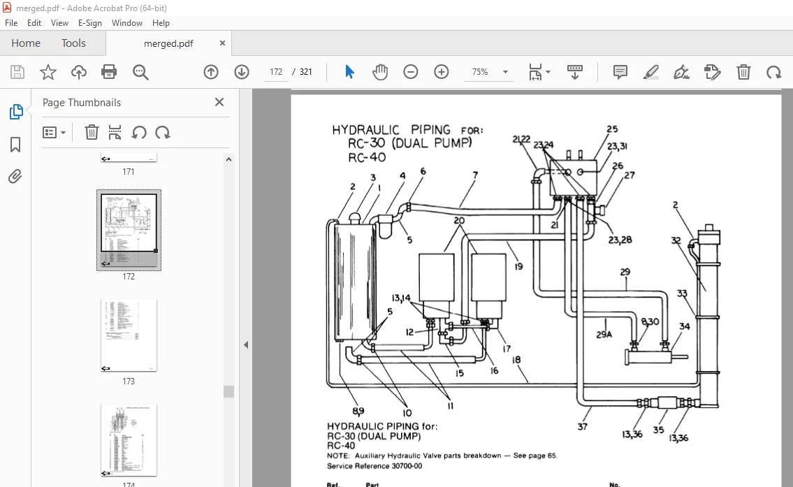
Dual Pump Hydraulic Piping RC-30,40 36
Hydraulic Control Valve 38
Hydraulic: Valve Mounting, Reservoir Mounting, Motor Mounting 39
Hydraulic Pump/Motor Assembly for P-25428 40
Pump/Motor Assembly for P-25428 41
Tilt Cylinder Assembly 42
Lift Cylinder – 3 Stage White Mast 44
Lift Cylinder – Prime-Mover Mast 46
Mast – Prime-Mover 48
Retractable Overhead Guard 51
Mast – Knickerbocker 52
Mast – White 54
G E SCR Electrical Schematic 56
Electrical Schematic Symbols 57
Control Wiring for G E Model EV-1 System 58
Power Wiring G E Model EV-1 60
G E Model EV-1 Control 62
Contactor Panel G E Model EV-1 63
EV-1 Forward/Reverse Contactor 64
EV-1 1A, P & FW Contactor 66
Control Handle Master Switch 68
Cold Storage Diagram/Components 69
Auxiliary Hydraulic Valve Parts Breakdown 71
Brudi Side Shifter 72
Hydraulic Cylinder for Brudi Side Shifter 73
Brudi Hose Reel Assembly for Prime-Mover Masts 74
BRudi Hose Reel 75
Gleason Hose Reel Assembly for 3 Stage Masts 76
Gleason Hose Reel 77
Service Guide 78
Front Cover 82
Warranty 83
To New Prime-Mover Owners 84
Contents 84
Operating Instructions 85
Preliminary Service 85
Operation 85
Controls 85
Key Switch 85
Dead Man Brake 85
Direction Control 85
Horn 86
Lift Lower Control 86
Tilt Control 86
Auxiliary Hydraulic Control 86
Service References 86
Periodic Maintenance Chart 87
Daily 87
Weekly 87
Annually 87
Monthly 87
Semi-Annually 87
Lubrication Chart 88
Maintenance Instructions 89
Battery 89
Electrical Wiring 89
Control Switches 89
Potentiometer 89
Deadman Brake 90
Interlock Switch 90
Steering Chain 90
Transmission Rollers 91
Contactor Points 91
Motor Commutator 91
Drive Gear Adjustments 91
Hydraulic System 91
Hydraulic Pump/Motor 91
Hydraulic Valve Switch 92
Lift Cylinder 92
Lift Chain 92
Tilt Cylinder 92
Articulating Plate 92
Service and Disassembly Instructions 93
Mast 93
Tilt Cylinder 93
Lift Cylinder 93
Floor Plate 94
Transmission Assembly 94
Articulating Plate 94
Support Wheel Steering Linkage 94
Drive Wheel 94
Drive Motor 95
Electrical Panels 95
Steering Gear Box 95
Lift Frame 95
Inner Column 95
Brake Discs 95
Parts Ordering Instructions 96
Field Modifications 96
Parts List Index 97
Main Frame, Shielding, Misc 99
Drive Mounting 101
24 Volt Transmission 103
Drive Motor Service Parts 105
Steering Linkage 106
Steering Assembly 107
Steering Reduction 108
Hydraulic Piping RC-20, 25, 30 (Single Pump) 109
Hydraulic Piping RC-30 (Dual) and RC-40 111
Hydraulic Valve (2 & 3 Spool) 113
Hydraulic: Valve Mounting, Reservoir Mounting, Motor Mounting 114
Hydraulic Pump 115
Motor for P-25428 Pump/Motor Assembly 116
Tilt Cylinder Assembly 117
Lift Cylinder 118
Lift Cylinder Assembly 120
Mast – 2 Stage 121
Knickerbocker Trirol 3 Mast 123
White Masts 125
Square “D” Power Wiring 126
Control Wiring for G E System 127
Auxiliary Hydraulic Valve Parts Breakdown 128
Brudi Sideshifter 129
Hydraulic Cylinder for Brudi Sideshifter 130
Brudi Hose Reel Assembly 131
Brudi Hose Reel 132
Cascade Hose Reel Assembly (for 3 Stage Masts) 133
Outboard Spring Style Hose Reels 134
Inboard Spring Style Hose Reels 134
Service Guide 135
Front Cover 137
Warranty 138
New Prime-Mover Owner 139
Contents 139
Specifications 139
Operating Rules and Instructions 140
Maintenance Chart 146
Lubrication Chart 147
Maintenance Instructions 148
Service and Disassembly Instructions 152
Parts Ordering Instructions 155
Parts List and Service Reference Index 156
Main Frame, Shielding, Misc 158
Drive mounting 160
Transmission Service Parts 162
Drive Motor Service Parts for D-25901 164
Brake Linkage 166
Steering Linkage 167
Steering Assembly 168
Steering Reduction 169
Hydraulic Piping, Single Pump 170
Hydraulic Piping, Dual Pump 172
Hydraulic Control Valve 174
Hydraulic: Valve Mounting, Reservior Mounting, Motor Mounting 175
Hydraulic Pump 176
Motor Assembly for P-25428 177
Tilt Cylinder Assembly 178
Lift Cylinder – White 3 Stage Mast 180
Lift Cylinder – Prime-Mover 182
Mast – 2 Stage Prime-Mover 184
Mast – 3 Stage Knickerbocker 188
Mast – 3 Stage White 190
G E SCR Electrical Schematic – Model EV-1 192
Electrical Schematic Symbols 193
Control Wiring for G E EV-1 System 194
Power Wiring for G E EV-1 System 196
Control, G E EV-1 198
Contactor Panel, G E EV-1 199
Control Handle, EV-1 A-25314 200
Auxiliary Hydraulic Valve Parts 201
Brudi Sideshifter 202
Brudi Sideshifter Cylinder Assembly 203
Brudi Hose Reel Assembly for Prime-Mover Masts 204
Brudi Hose Reel Assembly 205
Gleason Hose Reel Assemby for 3 Stage Masts 206
Gleason Hose Reel Assembly 207
Service Guide 208
Front Cover 215
Warranty 216
To New Owners 217
Operating Rules and Instructions 218
Lubrication Chart 223
Maintenance Instructions 224
Service and Disassembly Instructions 227
Parts Ordering Instructions 230
RC20 Truck Specifications 231
RC25 Truck Specifications 232
RC30 Truck Specifications 233
RC40 Truck Specifications 234
Figure # 1 Decal and Parts Assembly 235
Figure # 2 Parts List and Service Reference Index 236
Figure # 3 Shielding Assembly 238
Figure # 4 Drive Mounting 240
Figure # 5 14:1 Transmission Assembly with MKU-4005 Drive Motor 242
Figure # 6 Motor Assembly 244
Figure # 7 Brake Linkage 245
Figure # 8 Slave Cylinder Assembly 246
Figure # 9 Master Cylinder Assembly 247
Figure # 10 Steering Linkage 248
Figure # 11 Steering Assembly 249
Figure # 12 Power Steering Gear Box 250
Figure # 13 Torque Generator 251
Figure # 14 Forward Gear Reduction Steering Gear Box, Reverse Chain Reduction Steering Gear Box 252
Figure # 15 GE Electrical Schematic – Model EV-1 253
Figure # 16 Electrical Symbols 254
Figure # 17 Control Wiring for GE Model EV-1 System 255
Figure # 18 Power Component Assembly 256
Figure # 19 SCR and Contactor Panel Assembly 257
Figure # 20 EV-1 SCR Control 258
Figure # 21 Transformer Assembly 259
Figure # 22 Rectifier Heat Sink Assembly 260
Figure # 23 GE Contactor Assembly 261
Figure # 24 Power Steering Contactor Assembly 262
Figure # 25 GE Contactor Assembly 263
Figure # 26 Warning Light Assembly 264
Figure # 27 Connector Assembly 265
Figure # 28 Handle Assembly 266
Figure # 29 Master Control Switch Assembly 267
Figure # 30 Master Control Switch Assembly 268
Figure # 31 Cold Storage Diagram/Components 269
Figure # 32 Hydraulic Schematic 270
Figure # 33 Hydraulic Schematic Symbols 271
Figure # 34 Hydraulic Assembly RC-20, 25, 30 (2 stage) 272
Figure # 35 Hydraulic Assembly (3 stage) 274
Figure # 36 Hydraulic Assembly – Part # 1 275
Figure # 37 Hydraulic Assembly Part # 2 276
Figure # 38 Staging Cylinder Assembly 278
Figure # 39 Freelift Cylinder Assembly 279
Figure # 40 Hydraulic Assembly Part # 3 280
Figure # 41 Pump and Motor Assembly 281
Figure # 42 Motor Assembly 282
Figure # 43 Pump Assembly 283
Figure # 44 Valve Mounting Assembly 284
Figure # 45 Control Valve Assembly 285
Figure # 46 Control Valve Assembly 286
Figure # 47 Hydraulic Pump and Motor 287
Figure # 48 Pump Assembly 288
Figure # 49 Motor Assembly 289
Figure # 50 Motor Assembly 290
Figure # 51 Tilt Cylinder Assembly and Related Parts 291
Figure # 52 Tilt Cylinder Assembly 292
Figure # 53 Lift Cylinder and Related Parts 293
Figure # 54 2″ Lift Cylinder Assembly 294
Figure # 55 2 1/2″ Lift Cylinder Assembly 296
Figure # 56 2 3/4″ Lift Cylinder Assembly 298
Figure # 57 2 Stage Mast Assembly 300
Figure # 58 2 Stage Outer Column Assembly 301
Figure # 59 2 Stage Inner Column Assembly 302
Figure # 60 2 Stage Lift Cylinder and Related Parts 303
Figure # 61 Lift Frame and Load Backrest 304
Figure # 62 RC-20 (Only) Lift Frame and Load Backrest 305
Figure # 63 Mast Assembly (3 Stage) 306
Figure # 64 Lift Frame Assembly 307
Figure # 65 Inner Column Assembly (3 Stage) 308
Figure # 66 Freelift Cylinder Assembly (3 Stage) 309
Figure # 67 Intermediate Column Assembly (3 Stage) 310
Figure # 68 Outer Column Assembly (3 Stage) 311
Figure # 69 Fork Assembly 312
Figure # 70 Auxiliary Hydraulic Valve Parts Breakdown 313
Figure # 71 Brudi Sideshifter 314
Figure # 72 Hydraulic Cylinder for Brudi Sideshifter 315
Figure # 73 Gleason Hose Reel Assembly (3 Stage Masts) 316
Figure # 74 Gleason Hose Reel 35 Series 317
Figure # 75 Dual Elbow Swivel Assembly 318
Service Guide 320
DESCRIPTION:
BT Prime Mover RC Series Trucks RC-20 RC-25 RC-30 RC-40 Operating Maintenance & Parts Manual – PDF DOWNLOAD
The Prime-Mover Electric Truck which you have just purchased was carefully designed and manufactured to ensure minimum cost, maximum reliability, and easy service. Extensive testing and high standards of quality control assure that these standards are maintained.
- To keep your Prime-Mover truck in good condition the periodic maintenance and lubrication guide should be followed.Prime-Mover trucks are also backed by a network of dealers who were chosen for their experience and reliability.
- They will assist you in keeping your Prime-Mover truck in peak operating condition.If you will take a moment to record the information it will be of help to you when parts and service assistance is needed.
OPERATING RULES AND INSTRUCTIONS
OPERATOR QUALIFICATIONS
Only trained and authorized operators shall be permitted to operate a powered industrial truck. Operators of powered industrial trucks shall be qualified as to visual, auditory, physical, and mental ability to operate the equipment.
OPERATOR TRAINING
An effective operator training program should center around user company’s policies, operating conditions and trucks. The program should be presented completely to all new operators and not condensed for those claiming previous experience.
OPERATOR RESPONSIBILITY
Powered industrial truck operators shall abide by the following rules and practices.
GENERAL RULES AND PRACTICES
A. Safeguard the pedestrians at all times. Do not drive a truck up to anyone standing in front of a bench or other fixed object.
B.Do not allow anyone to stand or pass under the elevated portion of any truck, whether loaded or empty.
C. Unauthorized passengers shall not be permitted to ride.
D. Do not put any part of the body between the uprights of the mast or outside the running lines of the truck.
E.When the operator is dismounted and within 25 feet (7600mm) of the truck which remains in his view, the load engaging means shall be fully lowered, controls neutralized and brakes set to prevent movement.
S.V 20/01/2025