BT-Prime Mover PMX45 Electric Low Lift Pallet Truck Parts Manual 311230-000 PDF
$28.95
BT-Prime Mover PMX45 Electric Low Lift Pallet Truck Parts Manual 311230-000 – PDF DOWNLOAD
Manual Part no: 311230-000
Effective Serial Number PMX4531141001-UP
Description
BT-Prime Mover PMX45 Electric Low Lift Pallet Truck Parts Manual 311230-000 – PDF DOWNLOAD
FILE DETAILS:
BT-Prime Mover PMX45 Electric Low Lift Pallet Truck Parts Manual 311230-000 – PDF DOWNLOAD
Language : English
Pages : 282
Downloadable : Yes
File Type : PDF
IMAGES PREVIEW OF THE MANUAL:


TABLE OF CONTENTS:
BT-Prime Mover PMX45 Electric Low Lift Pallet Truck Parts Manual 311230-000 – PDF DOWNLOAD
Manual Part no: 311230-000
Effective Serial Number PMX4531141001-UP
Standard Codes 3
Warning Symbols 13
1 Warning Levels 13
Prohibitory Symbols 14
1 Ordinance Symbols 14
Safety 15
1 General Safety 15
Battery Safety 19
Static Safety 24
Welding Safety 25
Introduction, Service Manual 27
Contents, Section M 29
1 Machine Information 29
General Product Information 31
1 Truck Presentation 31
1 1 Truck Side Views 31
1 1 Intended Truck Application 32
1 2 Prohibited Truck Application 32
1 3 Truck Data 32
1 4 Truck Dimensions 33
1 5 Data Plate 34
2 Main Components 35
Inch and Metric (SAE) Fasteners 37
1 Introduction 37
2 Nomenclature, Threads 38
3 Strength Identification 39
4 Conversion of English and Metric Units 46
Technical Service Data 49
Ordering Spare Parts 51
Contents, Section P 53
1 Planned Maintenance 53
Introduction, Maintenance 55
1 Jacking Truck Off The Floor 56
1 1 Elevate Rear of Truck 56
1 1 Elevate Either Side of Truck 56
2 Lubricants 57
2 1 Standard 57
2 2 Corrosion 57
2 3 Cold Storage 58
Service Schedule 61
1 Planned Maintenance Schedule 61
2 Planned Maintenance Procedures 65
2 1 Services Performed Daily or Every 8 Operating Hours 65
2 1 1 Battery Discharge Indicator with lift interrupt (optional) 65
2 1 2 Hydraulic System 65
2 1 3 Frame/Sheet Metal 66
2 1 4 Wheels/Tires 66
2 1 5 Functions/Operations 66
2 2 Services Performed Monthly or Every 120 Operating Hours 67
2 2 1 Inspection 67
2 2 2 Transmission 67
2 2 3 Brakes 67
2 2 4 Battery 67
2 2 5 Electrical Connections 68
2 2 6 Main Contactor 68
2 2 7 Motor Brushes 68
2 2 8 Drive Motor 68
2 2 9 Hydraulic Reservoir 68
2 2 10 Frame Lube 69
2 2 11 Pivot Points 69
2 3 Services Performed Every 480 or 960 Operating Hours 70
2 3 1 Drive Motor 70
2 4 Services Performed Annually or Every 1440 Operating Hours 71
2 4 1 Inspection 71
2 4 2 Transmission 71
2 4 3 Battery 71
2 4 4 Hydraulic System 72
2 4 5 Brakes 72
Lubrication Chart 73
Oil and Grease Specifications 74
1 Approved Oils and Grease 74
2 Grease Location Points 74
Contents, Section S 75
1 Service Instructions 75
Chassis/Lift Frame 77
1 Pull rod 78
1 1 Removal 78
1 2 Inspection 79
1 3 Installation 80
2 Carrier Frame Bushings 82
Inspection Covers 83
1 General Information 83
Driver Controls 87
Decals 89
1 Decal with Protective Sheet 89
2 Decal without Protective Sheet 89
Motor Maintenance Schedule/ Troubleshooting 91
1 General Information 91
2 Operating Conditions 91
3 Troubleshooting 92
Pump Motor 99
1 Mounting Points 99
1 1 Removal 99
1 2 Installation 99
2 Pump Repair 100
2 1 Disassembly 101
3 Inspection and Troubleshooting 102
3 1 Drive End Head 102
3 2 Commutator End Head 102
3 3 Bearings 102
4 Brush Inspection 103
4 1 Brush Replacement Determination 103
4 2 Replacement Procedures 104
Drive Motor 107
1 Mounting Points 107
1 1 Drive Motor Brush 108
1 2 Drive Motor Removal 108
1 3 Drive Motor Installation 110
2 Component Repair 112
2 1 Motor Disassembly 114
3 Motor Inspection 115
3 1 External Motor 115
3 2 Brush and Commutator 115
3 3 Bearings 118
3 4 Armature Electrical Check 118
3 5 Frame and Field Service Recommendation 118
3 6 Assembly/Testing 119
Transmission 121
1 System Description 121
2 Troubleshooting 121
3 Transmission Mounting 122
3 1 Wrap Around Bumper 123
3 2 Guards 124
3 3 Removal 125
3 4 Installation 126
4 Transmission Repair 127
4 1 Disassembly 128
4 2 Reassembly 129
5 Axle Seal 131
5 1 Removal 131
5 2 Installation 131
Parking Brake System 133
1 Brake Theory of Operation 134
2 Brake Adjustment 135
3 Brake Shoe Removal / Installation 136
Drive Wheel 137
1 Removal 137
2 Installation 138
3 Tire Pressing Procedure 139
Support/Swivel Wheel (Optional) 141
1 Maintenance and Adjustments 143
1 1 Caster Adjustment 143
2 Troubleshooting 143
2 1 Stabilizing Caster 143
2 1 1 Caster Replacement 143
Fork Wheels 145
1 Removal/Installation 145
Steering 147
1 Control Handle Head 148
1 1 Removal 148
1 2 Installation 148
2 Driver Protection (Reverser) Assembly Replacement 149
3 Direction Control Switches 151
3 1 Removal 151
3 2 Installation 151
4 Raise, Lower, and Horn Switches 153
4 1 Removal 153
4 2 Installation 154
5 Potentiometer 155
5 1 Removal 155
5 2 Installation 156
6 Steering Stem 160
6 1 Removal 160
6 2 Installation 160
Electrical Functions 161
1 General 161
1 1 Adjustable Settings: 161
1 2 References 161
1 3 Key Switch S17 in the ON Position 161
1 4 Operating Arm in Drive Position, S10, Brake Switch Closed 162
1 5 Travel Request, Fork First 162
1 6 Travel Request, Forks Trailing 162
1 7 Reversing/Motor Brake Forks First Direction to Forks Trailing Direction 162
1 8 Reversing/Motor Brake Forks Trailing Direction to Forks First Direction 163
1 9 Reverser switch 163
1 10 Lifting Forks 163
1 11 Lowering Forks 163
1 12 Horn 164
1 13 Lift Interrupt 164
Electrical Panel Components 165
Electrical Symbols 167
Electrical Schematics 171
Circuit Diagram 1(3) 171
Circuit Diagram 2(3) 172
Circuit Diagram 3(3) 173
Battery 175
1 Removal 175
2 Installation 175
3 Battery Maintenance 176
3 1 Battery Inspection and Care 176
3 2 Battery Exterior Cleaning 177
3 3 Charging 177
4 Storage 178
5 Battery History Record 178
Swing Out Battery Pack 179
1 Battery Cable Routing Diagram 181
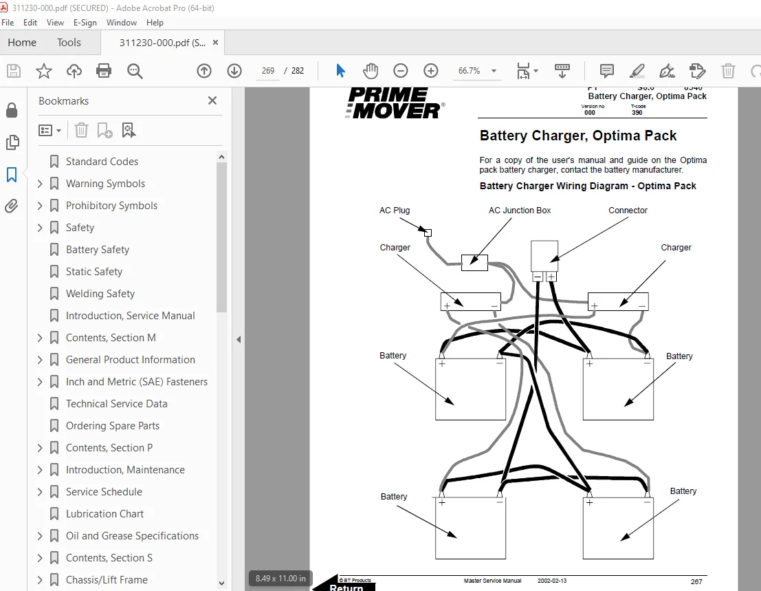
2 Charger Diagram 183
3 Troubleshooting 184
3 1 Electrical Testing 184
3 1 1 Equipment required: 184
3 1 2 Instructions 184
Battery Connector 191
1 Location 191
2 Inspection 191
3 Installation 192
Battery Controller/Hourmeter/ Lift Interrupt (Optional) 193
1 General Information 193
2 Electrical 194
2 1 Voltage 194
3 Battery Controller (BC) 195
3 1 General Information 195
3 1 1 Discharge Adjustment 195
3 2 Reset 197
3 3 Key Switch 197
3 4 Hourmeter 198
4 Troubleshooting 198
4 1 Battery Discharge Indicator (BDI) 198
4 1 1 No Reset 198
4 1 2 Reset After Break in Power 198
4 1 3 No Discharge, Gauge Does Not Run Down 199
4 1 4 No Lockout 199
4 1 5 No Lift 200
4 1 6 Early Lockout 200
4 1 7 LEDs Do Not Light 200
4 2 Hourmeter 201
4 2 1 No Display 201
4 2 2 Hourmeter Glass Icon Does Not Flash 201
4 2 3 Hourmeter Glass Icon Always Flashes 201
Battery Discharge Indicator / Hourmeter 203
1 General Information 203
2 Electrical 204
2 1 Voltage 204
3 Battery Discharge Indicator (BDI) 204
3 1 General Information 204
3 2 Key Switch 204
3 3 Hourmeter 205
4 Troubleshooting 205
4 1 Battery Discharge Indicator (BDI) 205
4 1 1 No Reset 205
4 1 2 Reset After Break in Power 206
4 1 3 No Discharge, Gauge Does Not Run Down 206
4 1 4 LEDs Do Not Light 206
4 2 Hourmeter 207
4 2 1 No Display 207
4 2 2 Hourmeter Glass Icon Does Not Flash 207
4 2 3 Hourmeter Glass Icon Always Flashes 207
Start/Stop Switches 209
1 General 209
1 1 Test/Inspection 209
2 Master Control On/Off Switch (S21) 211
2 1 Inspection 211
2 2 Removal 211
2 3 Installation 211
Transistor Controller 213
1 Basics Of Circuit Operation 213
1 1 Control Features 215
2 Maintenance 216
2 1 Safety 216
2 2 Cleaning 216
3 Motor Circuit 217
4 Control Circuit 218
5 Troubleshooting Guidelines 219
5 1 General 221
6 Shorts to Frame Test 222
7 Definitions 226
8 Diagnostics and Troubleshooting 227
8 1 Handset Diagnostics 227
8 2 Troubleshooting 227
8 3 Troubleshooting Chart 229
8 4 Technical Specification 234
8 5 Troubleshooting Chart Using Handset 235
Transistor Controller Troubleshooting 237
1 Troubleshooting Chart Index 237
2 Troubleshooting Charts 238
Hydraulic System 249
1 General 249
2 Troubleshooting 249
3 Schematic 251
4 Description 252
4 1 Lift 252
4 2 Lower 252
4 3 Relief Pressure 252
5 Maintenance 253
6 Lift Limit Switch 253
Hydraulic Pump 255
1 Removal 257
2 Disassembly 258
3 Inspection 259
4 Reassembly 260
5 Installation 262
6 Adjustments 263
6 1 Relief valve 264
6 2 Solenoid Operated Valve 264
Lift Cylinder 265
1 Cylinder Repair 266
1 1 Removal 266
1 2 Disassembly 267
1 3 Inspection 267
1 4 Assembly 267
1 5 Installation 268
Battery Charger, Optima Pack 269
Handset Operation 271
1 Operating Modes 274
2 Revert to Previous Settings 277
3 Handset Self Test 277
A 279
B 279
C 279
D 279
E 279
F 279
G 279
H 279
I 279
L 279
M 280
O 280
P 280
S 280
T 280
W 280
DESCRIPTION:
BT-Prime Mover PMX45 Electric Low Lift Pallet Truck Parts Manual 311230-000 – PDF DOWNLOAD
Manual Part no: 311230-000
Effective Serial Number PMX4531141001-UP
Introduction, Service Manual:
- The information in this Service Manual covers model PMX45.
- Federal and State laws require that operators be completely trained in the safe operation of trucks in accordance with OSHA regulation 1910.178.
- An Operator’s Manual is sent with every BT Prime-Mover lift truck when it is manufactured.
- This service manual is not a training manual. The information contained in this service manual is intended as a guide to help trained, qualified and authorized technicians safely service this truck.
- The Service Manual is divided into four separate sections, which cover needed information for servicing the truck type.
General Product Information:
1. Truck Presentation.
- The PMX45 is a battery powered walkie pallet truck intended solely to be operated handling pallets or similar load carriers indoors. The trucks are equipped with a steering arm with all the controls for operating within easy access. The trucks have maximum lifting capacities of up to 4500 pounds (2041 kg). Review data plate on the truck to note the maximum lifting capacity.
- The truck is equipped with a 24 volt electrical system. Truck speed is regulated by means of a transistor controller to provide infinite control of acceleration and speed while driving. Chassis/lift frame is raised by means of a hydraulic unit. The control of the lift/lower is done electrically with the push button on the steering arm. The trucks can be fitted with a battery pack and can be specially equipped to work in cold conditions.
S.V 11/01/2025