BT Prime-Mover PMX45 Electric Low Lift Pallet Truck Master Service Manual PDF
$28.95
BT Prime-Mover PMX45 Electric Low Lift Pallet Truck Master Service Manual – PDF DOWNLOAD
Effective Serial Number PMX4531141001 – UP
Part no: 311230-000
Description
BT Prime-Mover PMX45 Electric Low Lift Pallet Truck Master Service Manual – PDF DOWNLOAD
FILE DETAILS:
BT Prime-Mover PMX45 Electric Low Lift Pallet Truck Master Service Manual – PDF DOWNLOAD
Language : English
Pages : 302
Downloadable : Yes
File Type : PDF
IMAGES PREVIEW OF THE MANUAL:
TABLE OF CONTENTS:
BT Prime-Mover PMX45 Electric Low Lift Pallet Truck Master Service Manual – PDF DOWNLOAD
Effective Serial Number PMX4531141001 – UP
Part no: 311230-000
Front Cover 1
BT Standard Codes 3
Warning Symbols 15
1 Warning Levels 15
Prohibitory Symbols 16
1 Ordinance Symbols 16
Safety 17
1 General Safety 17
Battery Safety 21
Static Safety 26
Welding Safety 27
Introduction, Service Manual 29
Contents, Section M 31
1 Machine Information 31
General Product Information 33
1 Truck Presentation 33
1 1 Truck Side Views 33
1 1 Intended Truck Application 34
1 2 Prohibited Truck Application 34
1 3 Truck Data 34
1 4 Truck Dimensions 35
1 5 Data Plate 36
2 Main Components 37
Inch and Metric (SAE) Fasteners 41
1 Introduction 41
2 Nomenclature, Threads 42
3 Strength Identification 43
4 Conversion of English and Metric Units 49
Technical Service Data 51
Ordering Spare Parts 53
Contents, Section P 55
1 Planned Maintenance 55
Introduction, Maintenance 57
1 Safe Jacking Procedure 57
2 Lubricants 58
2 1 Cold Storage Conditioning 58
2 2 Electrical Component Cold Storage Conditioning 58
Service Schedule 59
1 Planned Maintenance Schedule 60
2 Planned Maintenance Procedures 63
2 1 Services Performed Daily or Every 8 Operating Hours 63
2 1 1 Battery Discharge Indicator with slow down 63
2 1 2 Hydraulic System 63
2 1 3 Frame/Sheet Metal 64
2 1 4 Functions/Operations 64
2 2 Services Performed Monthly or Every 120 Operating Hours 64
2 2 1 Inspection 64
2 2 2 Transmission 64
2 2 3 Brakes 64
2 2 4 Battery 65
2 2 5 Electrical Connections 65
2 2 6 Main Contactor 65
2 2 7 Motor Brushes 65
2 2 8 Drive Motor 65
2 2 9 Hydraulic Reservoir 65
2 2 10 Frame Lube 66
2 2 11 Pivot Points 66
2 3 Services Performed Quarterly or Every 360 Operating Hours 66
2 3 1 Wheels/Tires 66
2 3 2 Hydraulic System 66
2 3 3 Lift Cylinder Mounting 66
2 4 Services Performed Semi-Annually or Every 720 Operating Hours 67
2 4 1 Chassis 67
2 4 2 Drive Motor 67
2 4 3 Drive Gear 67
2 4 4 Brake 67
2 4 5 Steering Control Handle 67
2 4 6 Instrument Panel 68
2 4 7 Electrical Control System 68
2 4 8 Electrical Panel 68
2 4 9 Electronic Card 68
2 4 10 Hydraulic System 68
2 5 Services Performed Annually or Every 1440 Operating Hours 68
2 5 1 Inspection 68
2 5 2 Transmission 68
2 5 3 Battery 69
2 5 4 Hydraulic System 69
2 5 5 Brakes 69
Lubrication Chart 71
Oil and Grease Specifications 72
1 Approved Oils and Grease 72
Contents, Section S 73
1 Service Instructions 73
Troubleshooting Guidelines 75
1 General 75
2 Electrical 77
2 1 Shorts to Frame Test 77
3 Hydraulic 82
4 Definitions 83
Chassis/Lift Frame 85
1 Pull rod 86
1 1 Removal 86
1 2 Inspection 87
1 3 Installation 88
2 Carrier Frame Bushings 90
Inspection Covers 91
1 General Information 91
Mounting Points 95
1 Drive Motor Brush 96
2 Drive Motor Assembly 96
2 1 Removal 96
2 2 Installation 98
3 Pump Motor Assembly 100
3 1 Removal 100
3 2 Installation 100
Decals 101
1 Decal with Protective Sheet 101
2 Decal without Protective Sheet 101
Pump Motor 103
1 Component Repair 104
1 1 Disassembly 104
2 Inspection and Troubleshooting 106
2 1 Drive End Head 106
2 2 Commutator End Head 106
2 3 Bearings 106
3 Brush Inspection 107
3 1 Brush Replacement Determination 107
3 2 Replacement Procedures 108
Motor Maintenance Schedule/Troubleshooting 111
1 General Information 111
2 Operating Conditions 111
3 Troubleshooting 112
“E” Drive Motor 119
1 Component Repair 120
1 1 Motor Disassembly 120
2 Motor Inspection 122
2 1 External Motor 122
2 2 Brush and Commutator 122
2 3 Bearings 123
2 4 Armature Electrical Check 124
2 5 Commutator Undercut Guide 125
2 6 Frame & Field Service Recommendation 125
2 7 Assembly/Testing 126
“EE” Drive Motor 129
1 Component Repair 130
1 1 Motor Disassembly 130
2 Motor Inspection 131
Transmission 133
1 System Description 133
2 Troubleshooting 133
3 Axle Seal 134
3 1 Removal 134
3 2 Installation 134
4 Transmission Repair 136
4 1 Removal 137
4 2 Installation 137
4 3 Finger and Toe Guards 139
4 4 Wrap Around Toe Guard 140
5 Transmission Assembly 141
5 1 Disassembly 142
5 2 Reassembly 143
Parking Brake System 145
1 Brake Theory of Operation 146
2 Brake Adjustment 147
3 Brake Shoe Removal / Installation 148
Drive Wheel 149
1 Removal 149
2 Installation 150
3 Tire Pressing Procedure 151
Fork Wheels 153
1 Removal/Installation 153
Support/Swivel Wheel 155
1 Maintenance and Adjustments 157
1 1 Caster Adjustment 157
2 Troubleshooting 157
2 1 Stabilizing Caster 157
2 1 1 Caster Replacement 157
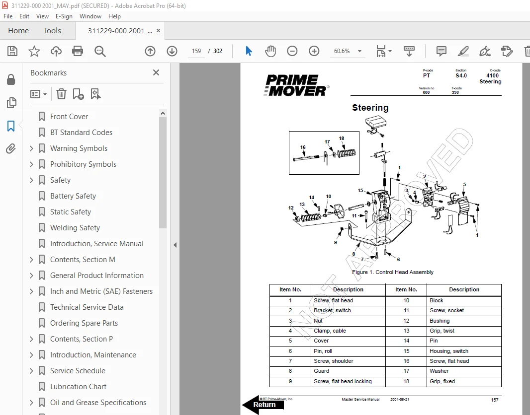
Steering 159
1 Control Handle Head 160
1 1 Removal 160
1 2 Installation 160
2 Direction Control Switches 162
3 Horn, Raise, and Lower Switches 166
4 Potentiometer 169
Battery 173
1 Removal 173
2 Installation 174
3 Battery Maintenance 175
3 1 Battery Inspection and Care 175
3 2 Battery Exterior Cleaning 176
3 3 Charging 176
4 Storage 177
5 Battery History Record 178
Swing Out Battery Pack 179
1 Battery Cable Routing Diagram 181
2 Charger Diagram 183
3 Troubleshooting 184
3 1 Electrical Testing 184
3 1 1 Equipment required: 184
3 1 2 Instructions 184
Battery Connector 191
1 Location 191
2 Inspection 192
3 Installation 193
Battery Controller/Hourmeter/ Lift Interrupt 195
1 General Information 195
2 Electrical 196
2 1 Voltage 196
3 Battery Controller (BC) 197
3 1 General Information 197
3 1 1 Discharge Adjustment 197
3 2 Reset 199
3 3 Key Switch 199
3 4 Hourmeter 199
4 Troubleshooting 200
4 1 Battery Discharge Indicator (BDI) 200
4 1 1 No Reset 200
4 1 2 Reset After Break in Power 200
4 1 3 No Discharge, Gauge Does Not Run Down 201
4 1 4 No Lockout 201
4 1 5 No Lift 201
4 1 6 Early Lockout 202
4 1 7 LEDs Do Not Light 202
4 2 Hourmeter 203
4 2 1 No Display 203
4 2 2 Hourmeter Glass Icon Does Not Flash 203
4 2 3 Hourmeter Glass Icon Always Flashes 203
Battery Discharge Indicator / Hourmeter 205
1 General Information 205
2 Electrical 205
2 1 Voltage 205
3 Battery Discharge Indicator (BDI) 206
3 1 General Information 206
3 2 Key Switch 206
3 3 Hourmeter 206
4 Troubleshooting 206
4 1 Battery Discharge Indicator (BDI) 207
4 1 1 No Reset 207
4 1 2 Reset After Break in Power 207
4 1 3 No Discharge, Gauge Does Not Run Down 208
4 1 4 LEDs Do Not Light 208
4 2 Hourmeter 208
4 2 1 No Display 208
4 2 2 Hourmeter Glass Icon Does Not Flash 208
4 2 3 Hourmeter Glass Icon Always Flashes 209
Start/Stop Switches 211
1 General 211
1 1 Test/Inspection 211
2 Master Control On/Off Switch (S21) 213
2 1 Inspection 213
2 2 Removal 213
2 3 Installation 213
Electrical System 215
1 Electrical Panel Components 215
2 List of Symbols 216
2 1 Circuit Diagram 1(3) 217
2 2 Circuit Diagram 2(3) 218
2 3 Circuit Diagram 3(3) 219
3 Function Description 220
3 1 General Information 220
3 2 Reference Information 220
3 3 Key Switch S17 in the ON Position 220
3 4 Operating Arm in Drive Position, S10, Brake Switch Closed 220
3 5 Driving, Fork Direction 221
3 6 Driving, Steer Wheel Direction 221
3 7 Reversing/Motor Brake Fork Direction to Steer Wheel Direction 221
3 8 Reversing/Motor Brake Steer Wheel Direction to Fork Direction 221
3 9 Reverser switch 221
3 10 Lifting Forks 222
3 11 Lowering Forks 222
3 12 Horn 222
3 13 Lift Interrupt 222
Transistor Controller 223
1 Maintenance 223
1 1 Safety 223
1 2 Cleaning 223
1 3 Diagnostics and Troubleshooting 224
1 3 1 Handset Diagnostics 224
1 3 2 Troubleshooting 224
2 Basics Of Circuit Operation 226
2 1 Control Features 228
3 Motor Circuit 230
4 Control Circuit 231
5 Diagnostics and Troubleshooting 233
5 1 1307 Programmer Diagnostics 233
5 2 Troubleshooting Chart 234
5 3 Technical Specification 238
5 4 Troubleshooting Chart Using Handset 239
Transistor Controller Troubleshooting 241
1 Troubleshooting Chart Index 241
2 Troubleshooting Charts 242
Contactor Panel 253
Hydraulic System 255
1 Hydraulic Schematic 255
2 General Information 255
3 Description 256
3 1 Lift 256
3 2 Lower 256
3 3 Relief Pressure 256
4 Maintenance 257
5 Adjustments 257
6 Lift Limit Switch 257
7 Troubleshooting 259
Hydraulic Pump 261
1 Removal 263
2 Disassembly 264
3 Inspection 265
4 Reassembly 266
5 Installation 268
6 Adjustments 270
6 1 Relief valve 270
6 2 Solenoid Operated Valve 271
Lift Cylinder 273
1 Cylinder Repair 274
1 1 Removal 274
1 2 Disassembly 275
1 3 Inspection 275
1 4 Assembly 275
1 5 Installation 276
Battery Charger 277
Handset Operation 291
1 Operating Modes 294
2 Revert to Previous Settings 297
3 Handset Self Test 297
Back Cover 302
S.V 01/02/2025