BT Prime Mover PE-60C HT-60C Electric Center Control Low Lift Truck Parts Manual PDF
$29.95
BT Prime Mover PE-60C HT-60C Electric Center Control Low Lift Truck Parts Manual – PDF DOWNLOAD
Description
BT Prime Mover PE-60C HT-60C Electric Center Control Low Lift Truck Parts Manual – PDF DOWNLOAD
FILE DETAILS:
BT Prime Mover PE-60C HT-60C Electric Center Control Low Lift Truck Parts Manual – PDF DOWNLOAD
Language : English
Pages : 231
Downloadable : Yes
File Type : PDF
IMAGES PREVIEW OF THE MANUAL:
TABLE OF CONTENTS:
BT Prime Mover PE-60C HT-60C Electric Center Control Low Lift Truck Parts Manual – PDF DOWNLOAD
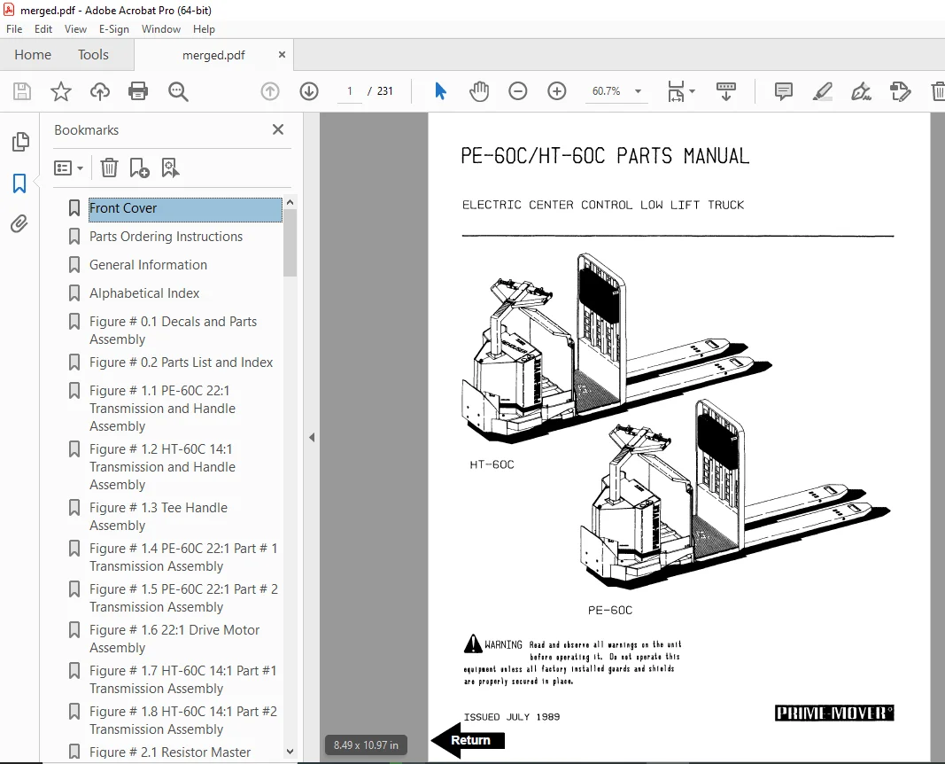
Front Cover 1
Parts Ordering Instructions 2
General Information 3
Alphabetical Index 4
Figure # 0 1 Decals and Parts Assembly 6
Figure # 0 2 Parts List and Index 8
Figure # 1 1 PE-60C 22:1 Transmission and Handle Assembly 10
Figure # 1 2 HT-60C 14:1 Transmission and Handle Assembly 12
Figure # 1 3 Tee Handle Assembly 14
Figure # 1 4 PE-60C 22:1 Part # 1 Transmission Assembly 16
Figure # 1 5 PE-60C 22:1 Part # 2 Transmission Assembly 18
Figure # 1 6 22:1 Drive Motor Assembly 20
Figure # 1 7 HT-60C 14:1 Part #1 Transmission Assembly 22
Figure # 1 8 HT-60C 14:1 Part #2 Transmission Assembly 24
Figure # 2 1 Resistor Master Control Switch 26
Figure # 2 2 Resistor 4 Speed Master Control Switch 28
Figure # 2 3 EV-100/EV-1 SCR Master Control Switch 30
Figure # 2 4 PE-60C Resistor Electrical Schematic 32
Figure # 2 5 Resistor Electrical Schematic Symbols 33
Figure # 2 6 PE-60C Third Speed Control Wiring 34
Figure # 2 7 12 Volt PE-60C Third Speed Power Component Wiring 36
Figure # 2 8 24 Volt PE-60C Third Speed Power Component Wiring 38
Figure # 2 9 Control Panel Assembly 40
Figure # 2 10 Contactor Assembly 42
Figure # 2 11 Forward & Rearward Contactor Assembly 44
Figure # 2 12 Third Speed Contactor Panel Assembly 46
Figure # 2 13 PE-60C Third Speed Contactor Assembly 48
Figure # 2 14 HT-60C Resistor Electrical Schematic 50
Figure # 2 15 Resistor Electrical Schematic Symbols 51
Figure # 2 16 HT-60C Third Speed Control Wiring 52
Figure # 2 17 HT-60C Third Speed Power Component Wiring 54
Figure # 2 18 HT-60C Resistor Control Panel Assembly 56
Figure # 2 19 HT-60C Third Speed Contactor Panel Assembly 58
Figure # 2 20 HT-60C Fourth Speed Control Wiring 60
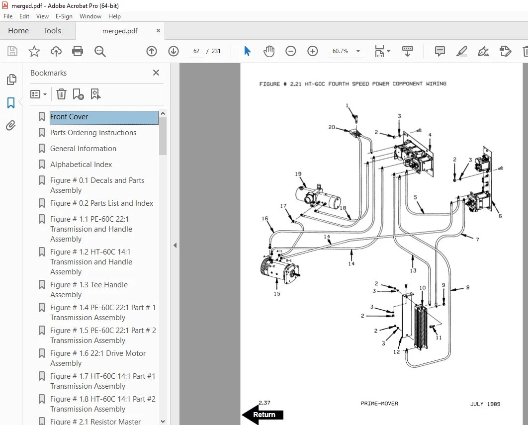
Figure # 2 21 HT-60C Fourth Speed Power Component Wiring 62
Figure # 2 22 HT-60C Fourth Speed Contactor Panel Assembly 64
Figure # 2 23 EV-100 SCR Trucks Electrical Schematic 66
Figure # 2 24 EV-100 SCR Truck Electrical Schematic Symbols 67
Figure # 2 25 EV-100 SCR Control Wiring 68
Figure # 2 26 HT-60C EV-100 SCR Two Speed Power Component Wiring 70
Figure # 2 27 EV-100 SCR Contactor Panel Assembly 72
Figure # 2 28 EV-100 SCR Forward & Rearward Contactor Assembly 74
Figure # 2 29 EV-100 1A Contactor Assembly 76
Figure # 2 30 HT-60C EV-100 SCR Two Speed Pump Contactor Panel Assembly 78
Figure # 2 31 EV-100 SCR Three Speed Power Component Wiring 80
Figure # 2 32 EV-100 SCR Three Speed Contactor Panel Assembly 82
Figure # 2 33 EV-100 SCR Two & Three Speed Control Panel 84
Figure # 2 34 Power Connector Assembly 86
Figure # 2 35 Hydraulic Pump Motor Assembly 88
Figure # 2 36 PE-60C Drive Motor Assembly 90
Figure # 2 37 HT-60C 14:1 Drive Motor Assembly 92
Figure # 2 38 Wiring Assembly for Cold Storage 94
Figure # 3 1 Hydraulic Schematic 96
Figure # 3 2 Hydraulic Schematic Symbols 97
Figure # 3 3 Hydraulic System 98
Figure # 3 4 Pump and Motor Assembly 100
Figure # 3 5 Lift Cylinder Assembly 102
Figure # 4 1 Shielding Assembly 104
Figure # 4 2 Carrier Frame Assembly 106
Figure # 4 3 Caster Assembly 108
Figure # 4 4 Lift Frame Assembly 110
Figure # 4 5 Pallet Entry Rollers 112
Figure # 4 6 Rider Compartment and Padding Assembly 114
Figure # 6 1 Special Tools and Lubrications 116
Numerical Index 119
Front Cover 133
Warranty 134
Parts Ordering Instructions 135
General Information 136
Figure # 1 Decal and Parts Assembly 138
Figure # 2 Parts List and Service Reference Index 140
Figure # 3 Shield Assembly 142
Figure # 4 Transmission and Handle Assembly 144
Figure # 5 Tee Handle Assembly 146
Figure # 6 3 Speed Master Control Switch Assembly 148
Figure # 7 4 Speed Master Control Handle Assembly 150
Figure # 8 PE-60C 22:1 Transmission Assembly 152
Figure # 9 PE-60C 22:1 Drive Motor Assembly 154
Figure # 10 Drive Motor 12 Volt 156
Figure # 11 Drive Motor 24 Volt 158
Figure # 12 HT-60C 14:1 Transmission Assembly 160
Figure # 13 Drive Motor 24 Volt 162
Figure # 14 PE-60C Electrical Schematic 164
Figure # 15 HT-60C Electrical Schematic 165
Figure # 16 Electrical Schematic Symbols 166
Figure # 17 PE-60C 3 Speed Control Wiring Harness 168
Figure # 18 12 Volt PE-60C 3 Speed Power Components 170
Figure # 19 24 Volt PE-60C 3 Speed Power Components 172
Figure # 20 PE-60C Control Panel Assembly 174
Figure # 21 GE Contactor Assembly 176
Figure # 22 GE Contactor Assembly 178
Figure # 23 PE-60C 3 Speed Panel Assembly 180
Figure # 24 HT-60C 3 Speed Control Wiring Harness 182
Figure # 25 HT-60C 3 Speed Power Components 184
Figure # 26 HT-60C Control Panel Assembly 186
Figure # 27 GE Contactor Assembly 188
Figure # 28 HT-60C 3 Speed Panel Assembly 190
Figure # 29 HT-60C 4 Speed Control Wiring Harness 192
Figure # 30 HT-60C 4 Speed Power Components 194
Figure # 31 HT-60C 4 Speed Panel Assembly 196
Figure # 32 Contactor Assembly 198
Figure # 33 Power Connector Assembly 200
Figure # 34 Wiring Assembly for Cold Storage 202
Figure # 35 Hydraulic Schematic 204
Figure # 36 Hydraulic Schematic Symbols 205
Figure # 37 Hydraulic System 206
Figure # 38 Hydraulic Pump and Motor Assembly 208
Figure # 39 Motor Assembly 210
Figure # 40 Cylinder Assembly 212
Figure # 41 Lift Frame Assembly 214
Figure # 42 Carrier Frame Assembly 216
Figure # 43 Spring Loaded Caster Assembly 218
Figure # 44 Pallet Entry Rollers 220
Numerical Index 222
DESCRIPTION:
BT Prime Mover PE-60C HT-60C Electric Center Control Low Lift Truck Parts Manual – PDF DOWNLOAD
PARTS ORDERING INSTRUCTIONS :
HOW TO ORDER:
- When you order, supply the part number, quantity, model and serial numbers of your machine. Supplying this information will assure prompt, efficient handling of your order. The pictorial reference number is not needed and including it can only add confusion.
- Since your dealer carries many parts in stock and maintains up-to-date prices on all parts, he will be able to process your order immediately. If, for some reason, the part is not in stock, he will order it from the factory. In either event, he maintains a current file of service manuals, which give all available parts ordering or technical information.
- All prices are FOB factory in Muscatine, Iowa. Shipping charges are added to the price of the part shipping from the factory.
WHERE TO ORDER:
Always order parts from the dealer who sold you your Prime-Mover. If it is necessary for the dealer to order parts from the factory, he is able to get prompt service for you. Parts are shipped in accordance with shipping instructions given on the order.
S.V 12/01/2025