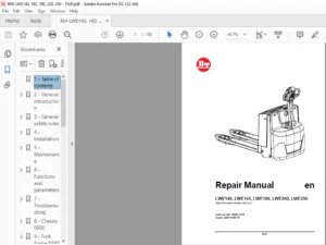
BT Prime-Mover PE-45 PE-45R PE-45C PE-60 PE-60R PL-45 HT-45 HT-60 Truck Operating Maintenance & Parts Manual PDF
$28.95
BT Prime-Mover PE-45 PE-45R PE-45C PE-60 PE-60R PL-45 HT-45 HT-60 Truck Operating Maintenance & Parts Manual – PDF DOWNLOAD
Description
BT Prime-Mover PE-45 PE-45R PE-45C PE-60 PE-60R PL-45 HT-45 HT-60 Truck Operating Maintenance & Parts Manual – PDF DOWNLOAD
FILE DETAILS:
BT Prime-Mover PE-45 PE-45R PE-45C PE-60 PE-60R PL-45 HT-45 HT-60 Truck Operating Maintenance & Parts Manual – PDF DOWNLOAD
Language : English
Pages : 122
Downloadable : Yes
File Type : PDF
IMAGES PREVIEW OF THE MANUAL:
TABLE OF CONTENTS:
BT Prime-Mover PE-45 PE-45R PE-45C PE-60 PE-60R PL-45 HT-45 HT-60 Truck Operating Maintenance & Parts Manual – PDF DOWNLOAD
Front Cover 1
Warranty 2
To New Prime-Mover Owners 3
Preliminary Service 3
Operation 3
Warning 4
Operating Rules and Instructions 5
Operator Qualifications 5
Operator Training 5
Operator Responsibility 5
General Rules and Practices 5
Traveling 5
Loading 6
Operator Care of the Truck 6
Controls and Safety Equipment 7
Horn Switch 7
Raise Switch 7
Lower Switch 7
Third Speed Control Switch 7
Key Switch 7
Battery Discharge Indicator 7
Hourmeter 8
Safety Interlock Switch 8
Deadman Brake 8
Direction Control Handle 8
Direction Control 8
Resistor Control 8
SCR Control System 8
Periodic Maintenance Chart 9
Lubrication Chart 10
Maintenance Instructions 11
Battery 11
Theory of Electrical Operations 11
Control Switches 11
Power Wiring 11
Control Wiring 12
Lift Limit Switch 12
Mechanical Brake 12
Interlock Switch 13
Transmission Rollers 13
Contactor Points 13
Motor Commutator 13
60 Series Only Pull Rod Assembly/Adjustment 13
Hydraulic System 14
Hydraulic Pump/Motor 14
Hydraulic Filter 14
Pressure Relief Valve Adjustment 14
Service and Disassembly Instructions 15
Contactor Points 15
Flush Grease Fittings 15
Remove Handle and Transmission Assembly 15
Handle and Transmission Assembly 15
Disassembly 15
Assembly 16
Drive Wheel 16
Drive Motor 16
Assembly 16
Adjustment of Backlash for 22:1 Transmission 16
Gear Case Guide Ring 17
22:1 Transmission Assembly (Single Disc Brake Assembly) 17
Assembly of Drive Motor 17
22:1 Transmission Assembly (Multiple Disk Brake Assembly) 18
Assembly of Drive Motor 18
Mechanical Brake 19
Interlock Switch 20
Assembly of 14:1 Transmission 20
Directional Control Switch 22
Master Switch 22
Disassembly 22
Assembly 23
Electrical Panel Contactors 23
Disassembly 23
Assembly 23
Lift Frame 24
Hydraulic Pump 24
Release Valve and Solenoid 24
Hydraulic Cylinders 24
Contactor Assembly 24
Connections 24
Maintenance and Adjustment 24
Power Contacts 24
Disassembly 24
Inspection 25
Assembly 25
Parts Ordering Instructions 26
Field Modifications 26
PE-45 Electric Low Lift Pallet Truck Specifications 27
PE-45R Electric Low Lift Pallet Truck Specifications 28
PE-60 Electric Low Lift Pallet Truck Specifications 29
PE-60R Electric Low Lift Pallet Truck Specifications 30
HT-45 Electric End Controlled Low Lift Pallet Truck Specifications 31
HT-60 Electric End Controlled Low Lift Pallet Truck Specifications 32
Parts Information 33
Figure 1 Decal and Parts Assembly 33
Figure 2 Part List and Service Reference Index 34
Figure 3 Shield Assembly 36
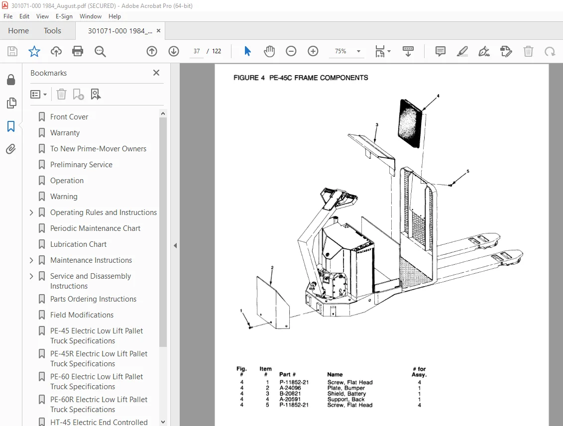
Figure 4 PE45C Frame Components 37
Figure 5 PE45/60 Carrier Frame Assembly 38
Figure 6 PE45/60 22:1 Handle and Transmission Assembly 39
Figure 7 PE45C 22:1 Transmission and Handle Assembly 40
Figure 8 PE45/50 Handle Assembly 41
Figure 9 PE45C Handle Assembly 42
Figure 10 Master Control Switch Assembly 43
Figure 11 Master Control Switch Assembly 44
Figure 12 Master Control Switch Assembly 45
Figure 13 Master Control Switch Assembly 46
Figure 14 PE45/60 12 Volt 22:1 Transmission Assembly Part # 1 47
Figure 15 PE45/60 12 Volt 22:1 Transmission Assembly Part # 2 48
Figure 16 Drive Motor Assembly 49
Figure 17 12 Volt Drive Motor Assembly 50
Figure 18 24 Volt Drive Motor 51
Figure 19 PE45/60 24 Volt and PE45R/60R 12/24 Volt Multiple Disc Brake Transmission Assembly 52
Figure 20 Drive Motor Assembly 54
Figure 21 Drive Motor, 12 Volt 55
Figure 22 Drive Motor, 12 Volt 56
Figure 23 HT45/60 Transmission and Handle Assembly 57
Figure 24 HT45C 14:1 Transmission and Handle Assembly 58
Figure 25 HT45/80 14:1 Transmission Assembly with MEA-4023 Drive Motor 60
Figure 26 14:1 Motor Assembly 62
Figure 27 Spring Loaded Caster Assembly 63
Figure 28 Electrical Symbols 64
Figure 29 PE/PL Electrical Schematic 65
Figure 30 Control Wiring Harness Assembly 66
Figure 31 Riding Control Wiring Harness Assembly 67
Figure 32 PE/PL Power Component Assembly 68
Figure 33 Control Panel Assembly 69
Figure 34 G E Contactor Assembly 70
Figure 35 G E Contactor Assembly 71
Figure 36 3rd Speed Panel Assembly 72
Figure 37 Cableform 3rd Speed Panel Assembly 73
Figure 38 Contactor Assembly (Cableform) 74
Figure 39 HT45 & 60 Electrical Schematic 75
Figure 40 Control Wiring Harness Assembly 76
Figure 41 HT45/60 Riding Control Wiring 77
Figure 42 HT45/60 Power Component Assembly 78
Figure 43 HT45/60 Control Panel Assembly 79
Figure 44 3rd Speed Panel Assembly 80
Figure 45 G E Contactor Assembly 81
Figure 46 Dynamic Brake Control Wiring Assembly 82
Figure 47 Model 50 SCR, 24 Volt, Electrical Schematic 83
Figure 48 G E Model 50 SCR Contactor Panel Wiring Diagram 84
Figure 49 G E Model 50 SCR Panel Wiring Diagram 85
Figure 50 G E Model 50 SCR Control Wiring 86
Figure 51 Model 50 SCR Power Wiring (24 Volt) 87
Figure 52 Model 50 SCR Panel Assembly 88
Figure 53 Model SCR Contactor Panel 89
Figure 54 G E Model SCR Contactor – Forward/Reverse & 1A 90
Figure 55 Pump Cont Panel Assembly 91
Figure 56 EV-1 SCR Electrical Schematic 92
Figure 57 Model EV-1 Control Wiring Harness Assembly 93
Figure 58 EV-1 Power Component Assembly 94
Figure 59 EV-1 Contactor Panel Assembly 95
Figure 60 G E Contactor Assembly 96
Figure 61 G E Contactor Assembly 97
Figure 62 EV-1 Pump Contactor Panel 98
Figure 63 EV-1 SCR Control 99
Figure 64 Transformer Assembly 100
Figure 65 Rectifier Heat Sink Assembly 101
Figure 66 Power Connector Assembly 102
Figure 67 Hydraulic Schematic 103
Figure 68 Hydraulic Schematic Symbols 104
Figure 69 Hydraulic System 105
Figure 70 Hydraulic Pump and Motor Assembly 106
Figure 71 Motor Assembly 108
Figure 72 Cylinder Assembly 109
Figure 73 PE-45, PE-45C, PE-45R, HT-45 Lift Frame Assembly 110
Figure 74 PE-60, HT-60 Lift Frame Assembly 112
Figure 75 PL-45 Lift Frame Assembly 115
Figure 76 Foot Pedal Assembly 116
Figure 77 Pallet Entry Roller Assembly 117
Figure 78 PE/HT 45 & 60 Rider Platform 118
Figure 79 Skid Adapter and Package Guard Assembly 119
Figure 80 Removable Load Bucket Rest 120
Service Guide 121
DESCRIPTION:
BT Prime-Mover PE-45 PE-45R PE-45C PE-60 PE-60R PL-45 HT-45 HT-60 Truck Operating Maintenance & Parts Manual – PDF DOWNLOAD
OPERATING RULES AND INSTRUCTIONS
OPERATOR QUALIFICATIONS
Only trained and authorized operators shall be permitted to operate a powered industrial truck. Operators of powered industrial trucks shall be qualified as to visual, auditory, physical, and mental ability to operate the equipment.
OPERATOR TRAINING
An effective operator training program should center around user company’s policies, operating conditions and trucks. The program should be presented completely to all new operators and not condensed for those claiming previous experience.
OPERATOR RESPONSIBILITY
Powered industrial truck operators shall abide by the following rules and practices.
GENERAL RULES AND PRACTICES
A. Safeguard the pedestrians at all times. Do not drive a truck up to anyone standing in front of a bench or other fixed object.
B. Do not allow anyone to stand or pass under the elevated portion of any truck, whether loaded or empty.
C. Unauthorized passengers shall not be permitted
to ride.
D. Do not put any part of the body between the uprights of the mast or outside the running lines of the truck.
E. When the operator is dismounted and within 25 feet (7.60 m) of the truck which remains in his view the load engaging means shall be fully lowered, controls neutralized and brakes set to prevent movement.
F. A powered industrial truck is unattended when the operator is 25 feet (7.60 m) or more from the truck which remains in view, or whenever the operator leaves the truck and it is not in his view. When a powered industrial truck is to be left unattended:
1. Stop truck.
2. Lower the forks.
3. Place directional controls in neutral.
4. Apply the parking brake.
5. Turn off power.
6. Turn off the control circuit.
7. Block wheels if truck is on slight incline.
S.V 04/02/2025