BT Prime-Mover OE Series Truck OE-30B Operating Maintenance & Parts Manual PDF
$28.95
BT Prime-Mover OE Series Truck OE-30B Operating Maintenance & Parts Manual – PDF DOWNLOAD
Description
BT Prime-Mover OE Series Truck OE-30B Operating Maintenance & Parts Manual – PDF DOWNLOAD
FILE DETAILS:
BT Prime-Mover OE Series Truck OE-30B Operating Maintenance & Parts Manual – PDF DOWNLOAD
Language : English
Pages : 170
Downloadable : Yes
File Type : PDF
IMAGES PREVIEW OF THE MANUAL:
TABLE OF CONTENTS:
BT Prime-Mover OE Series Truck OE-30B Operating Maintenance & Parts Manual – PDF DOWNLOAD
Front Cover 1
Warranty 2
New Owners 3
Contents 3
Preliminary Service 3
Operation 3
Operating Rules and Instructions 4
Lubrication Chart 9
Maintenance Instructions 10
Service and Disassembly Instructions 13
Parts Ordering Instructions 15
Truck Specifications 17
Figure # 1 Decal and Parts Assembly 20
Figure # 2 Parts List and Service Reference Index 22
Figure # 3 Shielding Assembly 24
Figure # 4 Transmission Installation Assembly 25
Figure # 5 Transmission Assembly 14:1 26
Figure # 6 Motor Assembly 28
Figure # 7 Motor Assembly 29
Figure # 8 Brake Cylinder Assembly 30
Figure # 9 Wiring Assembly Schematic 32
Figure # 10 Electrical Schematic Symbols 33
Figure # 11 Wiring Diagram Part # 1 34
Figure # 12 Wiring Diagram Part # 2 36
Figure # 13 Power Component Wiring 37
Figure # 14 SCR and Contactor Panel Assembly 38
Figure # 15 EV-1 SCR Control 39
Figure # 16 Transformer Assembly 40
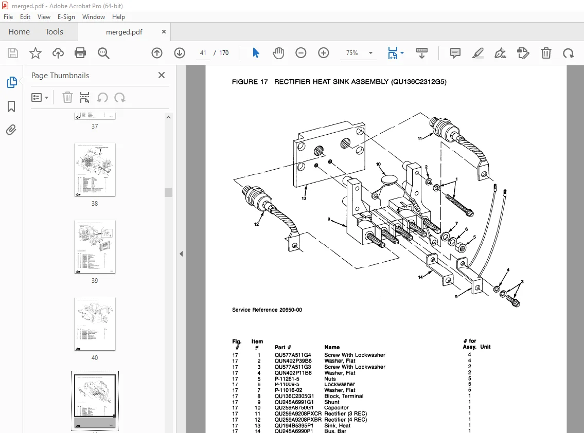
Figure # 17 Rectifier Heat Sink Assembly 41
Figure # 18 GE Contactor Assembly 42
Figure # 19 Power Steering Contactor Assembly 43
Figure # 20 GE Contactor Assembly 44
Figure # 21 Warning Light Assembly 45
Figure # 22 Connector Assembly 46
Figure # 23 Hydraulic Assembly 47
Figure # 24 Hydraulic Schematic 48
Figure # 25 Hydraulic Schematic Symbols 49
Figure # 26 Hydraulic Assembly Part # 1 50
Figure # 27 Pump and Motor Assembly 51
Figure # 28 Motor Assembly 52
Figure # 29 Torque Generator 53
Figure # 30 Hydraulic Assembly Part # 3 54
Figure # 31 Hydraulic Assembly Part # 4 55
Figure # 32 Hydraulic Pump and Motor Assembly 56
Figure # 33 Motor Assembly 57
Figure # 34 Flow Control Valve 58
Figure # 35 Hydraulic Assembly Part # 5 59
Figure # 36 Power Steering Control Assembly Part # 1 60
Figure # 37 Power Steering Control Assembly Part # 2 62
Figure # 38 2 Stage Mast Assembly 63
Figure # 39 Lift Platform Assembly Part # 1 64
Figure # 40 Lift Platform Assembly Part # 2 66
Figure # 41 Handle Assembly 67
Figure # 42 Master Control Switch Assembly 68
Figure # 43 Pallet Clamp Assembly 69
Figure # 44 2 Stage Inner Column Assembly 70
Figure # 45 2 Stage Outer Mast Assembly 71
Figure # 46 Staging Cylinder Assembly 72
Figure # 47 3 Stage Mast Assembly 73
Figure # 48 3 Stage Inner Column Assembly 74
Figure # 49 3 Stage Freelift Cylinder Assembly 75
Figure # 50 Freelift Cylinder Assembly 76
Figure # 51 3 Stage Intermediate Column Assembly 77
Figure # 52 3 Stage Outer Column Assembly 78
Figure # 53 Frame Assembly 79
Service Guide 80
Back Cover 82
Front Cover 83
Warranty 84
To New Prime-Mover Owners 85
Contents 85
Preliminary Service 85
Operation 85
Operating Rules and Instructions 86
Operator Qualifications 86
Operator Training 86
Operator Responsibility 86
General Rules and Practices 86
Traveling 86
Loading 87
Operator Care of the Truck 87
Safety Belt and Lanyard (Optional) 88
Controls 88
Horn 88
Lift/Lower Control 88
Battery Discharge Indicator (Optional) 88
Hourmeter (Optional) 88
Key Switch 88
Dead Man Brake 88
Direction Control 89
SCR Control System 89
Pallet Clamp 89
Steering 89
Emergency Disconnect 89
High Speed Travel Limit 89
Periodic Maintenance Chart 90
Lubrication Chart 91
Maintenance Instructions 92
Battery 92
Electrical Wiring 92
Control Switches 92
Potentiometer 93
Deadman Brake 93
Interlock Switch 93
Transmission Rollers 93
Contactor Points 93
Motor Commutator 94
Hydraulic System 94
Hydraulic Pump/Motor 94
Lift Cylinder 94
Control Valve 94
Pressure Switch 94
Lift Chain 94
Service and Disassembly Instructions 95
Operator Platform 95
Mast 95
Inner Column 95
Lift Cylinder (Removal) 95
Lift Cylinder (Internal Disassembly) 95
Transmission Assembly 95
Drive Wheel 96
Drive Motor 96
Brake Discs 96
Steering Cables 96
Electrical Panels 96
Parts Ordering Instructions 97
Field Modifications 97
OE-30B Electric Counterbalanced Order Selector Specifications 99
Figure # 1 Decal and Part Assembly 102
Figure # 2 Parts List and Service Reference Index 104
Figure # 3 Shield Assembly 106
Figure # 4 Transmission Installation Assembly 107
Figure # 5 Transmission Assembly 14:1 108
Figure # 6 Motor Assembly 110
Figure # 7 Motor Assembly 111
Figure # 8 Brake Cylinder Assembly 112
Figure # 9 Wiring Assembly Schematic 114
Figure # 10 Electrical Schematic Symbols 115
Figure # 11 Wiring Diagram Part 1 Frame 116
Figure # 12 Wiring Diagram Part 2 Platform 118
Figure # 13 Power Component Wiring 119
Figure # 14 SCR and Contactor Panel Assembly 120
Figure # 15 EV-1 SCR Control 121
Figure # 16 Transformer Assembly 122
Figure # 17 Rectifier Heat Sink Assembly 123
Figure # 18 G E Contactor Assembly 124
Figure # 19 Power Steering Contactor Assembly 125
Figure # 20 G E Contactor Assembly 126
Figure # 21 Warning Light Assembly 127
Figure # 22 Connector Assembly 128
Figure # 23 Hydraulic Assembly 129
Figure # 24 Hydraulic Schematic 130
Figure # 25 Hydraulic Schematic Symbols 131
Figure # 26 Hydraulic Assembly Part 1 132
Figure # 27 Power Steering Pump and Motor Assembly 133
Figure # 28 Power Steering Pump Assembly 134
Figure # 29 Power Steering Motor Assembly 135
Figure # 30 Torque Generator Assembly 136
Figure # 31 Hydraulic Assembly Part # 2 137
Figure # 32 Hydraulic Assembly Part # 3 138
Figure # 33 Hydraulic Pump and Motor 139
Figure # 34 Pump Assembly 140
Figure # 35 Motor Assembly 141
Figure # 36 Motor Assembly 142
Figure # 37 Flow Control Valve 143
Figure # 38 Hydraulic Assembly Part # 4 144
Figure # 39 Power Steering Control Assembly Part # 1 146
Figure # 40 Power Steering Control Assembly Part # 2 148
Figure # 41 2 Stage Mast Assembly 149
Figure # 42 Lift Platform Assembly Part # 1 150
Figure # 43 Lift Platform Assembly Part # 2 152
Figure # 44 Handle Assembly 153
Figure # 45 Master Control Switch Assembly 154
Figure # 46 Master Control Switch Assembly 155
Figure # 47 Pallet Clamp Assembly 156
Figure # 48 2 Stage Inner Column Assembly 157
Figure # 49 2 Stage Outer Column Assembly 158
Figure # 50 Staging Cylinder Assembly 159
Figure # 51 3 Stage Mast Assembly 160
Figure # 52 Stage Inner Column Assembly 161
Figure # 53 3 Stage Free Lift Cylinder Assembly 162
Figure # 54 Free Lift Cylinder Assembly 163
Figure # 55 3 Stage Intermediate Column Assembly 164
Figure # 56 3 Stage Outer Column Assembly 165
Figure # 57 Frame Assembly 166
Service Guide 168
Back Cover 170
DESCRIPTION:
BT Prime-Mover OE Series Truck OE-30B Operating Maintenance & Parts Manual – PDF DOWNLOAD
OPERATING RULES AND INSTRUCTIONS
OPERATOR QUALIFICTIONS
Only trained and authorized operators shall be permitted to operate a powered industrial truck. Operators of powered industrial trucks shall be qualified as to visual, auditory, physical, and mental ability to operate the equipment.
OPERATOR TRAINING
An effective operator training program should center around user company’s policies, operating condi- tions and trucks. The program should be presented completely to all new operators and not condensed for those claiming previous experience.
OPERATOR RESPONSIBILITY
Powered industrial truck operators shall abide by the following rules and practices.
GENERAL RULES AND PRACTICES
A. Safeguard the pedestrians at all times. Do not drive a truck up to anyone standing in front of a bench or other fixed object.
D. Do not allow anyone to stand or pass under the elevated portion of any truck, whether loaded or empty.
C. Unauthorized passengers shall not be permitted to ride.
D. Do not put any part of the body between the uprights of the mast or outside the running lines of the truck.
E. when the operator is dismounted and within 25 feet (7.60 m) of the truck which remains in his view, the load engaging means shall be fully lowered, controls neutralized and brakes set to prevent movement. F. A powered industrial truck is unattended when the operator is 25 feet (7.60 m) or more from the truck which remains in view, or whenever the operator leaves the truck and it is not in his view.
S.V 02/02/2025