BT Prime-Mover OE-35 Electric Order Selector Repair Manual PDF
$31.95
BT Prime-Mover OE-35 Electric Order Selector Repair Manual – PDF DOWNLOAD
Manual Part Number 301460-001
Description
BT Prime-Mover OE-35 Electric Order Selector Repair Manual – PDF DOWNLOAD
FILE DETAILS:
BT Prime-Mover OE-35 Electric Order Selector Repair Manual – PDF DOWNLOAD
Language : English
Pages : 628
Downloadable : Yes
File Type : PDF
IMAGES PREVIEW OF THE MANUAL:
TABLE OF CONTENTS:
BT Prime-Mover OE-35 Electric Order Selector Repair Manual – PDF DOWNLOAD
Front Cover 1
Index 2
Specifications 3
1 0 Electrical 3
2 0 Speeds 3
3 0 Hydraulics 4
4 0 Tires and Wheels 4
5 0 Fluids and Lubricants 4
6 0 SCR Card Settings 4
7 0 Torque 5
Lubrication Chart 6
Planned Maintenance Schedule 7
Adjustments 8
1 0 Brake 8
3 0 Brake Interlock Switch 8
5 0 Steering 8
6 0 Lift Chains 9
11 0 Speed Limiting Switch 9
12 0 SCR Card Trimpots 9
18 0 Gate Switch 9
19 0 Potentiometer 9
Load Wheel Replacement 10
Drive Tire Replacement 10
Removal of Plastic Dash Panel 11
Motor Service Instructions 12
Cleaning 12
Visual Inspection 12
Testing 13
Armature 14
Frame and Field Service Notes 15
Field Coil Installation 15
Assembly and Testing 15
Service Procedures 16
Troubleshooting 17
Drive Motor Assembly 24
Lift Motor Assembly 25
Steering Pump Motor Assembly 26
Electric Motor Specification 31
2 0 Drive Motor 31
3 0 Lift Motor 31
4 0 Steering Motor 31
Instructions – EV100 LX/LXT SCR Controls 35
Basics of Circuit Operation 37
Control Features 38
Oscillator 38
Current Limit 38
Plugging 39
Pedal Position Plug 39
Ramp Start 39
Full Power Transition 39
Control Acceleration and 1A Time 39
1A Current Drop Out 39
Static Return to Off 39
Accelerator Volts Hold-Off 39
Coil Driver Modules 40
1A Thermal Hold-Off 40
Must Pulse to Time 40
Pulse Monitor Trip (PMT) 40
Thermal Protector (TP) 40
Low Voltage 41
Field Weakening 41
Regenerative Braking 41
Dual Motor Operation 41
Electrical System Troubleshooting 42
Control Circuits and Power Circuits 43
Terminal Connection for LX/LXT Logic Cards 44
Instructions – Dash Display 46
Application 46
Function Set-Up Procedures 50
Checking Components 90
Main Logic Card 90
Capacitor 1C 91
Contactors F, R, 1A, SP, RW, D, Regen and P 91
Potentiometer in Accelerator 91
SCR’s (1 Rec, 2 Rec, 5 Rec) 91
Rectifiers (3 Rec, 4 Rec, Diode Blocks) 93
Thermal Protector (TP) 93
Filter Blocks 93
1X Choke and Reactor T3 – T4 94
Replacement of EV-100 Components 95
Capacitor 95
22 Rec, 23 Rec and 25 Rec 95
Instructions – EV100 Plugs 96
General 96
Procedures 96
Troubleshooting Chart – Electrical 98
7 1 Emergency Disconnect Contactor 98
7 2 Steering and Brake Release Pump 100
7 3 Travel 101
7 4 Lift 103
7 5 Lowering 105
Hydraulic 107
1 0 Lift System Pump 107
2 0 Steering System Pump 111
5 0 Solenoid Valves 115
6 0 Hydraulic System Troubleshooting 116
Theory of Operation – Lift/Lower 116
Theory of Operation – Power Steering 117
Theory of Operation – Brake Release 117
6 1 Lift 119
Mast 121
1 0 Shimming 121
2 0 Mast Removal, Installation, Disassembly and Assembly 128
Jacking and Hoisting 137
Transmission 138
1 0 Removal 138
2 0 Disassembly and Repair 139
3 0 Installation 146
Back Cover 148
Front Cover 149
Index 150
Specifications 151
1 0 Electrical 151
2 0 Speeds 151
3 0 Hydraulics 152
4 0 Tires and Wheels 152
5 0 Fluids and Lubricants 152
6 0 SCR Card Settings 152
7 0 Torque 153
Lubrication Chart 154
Adjustments 156
1 0 Brake 156
3 0 Brake Interlock Switch 156
5 0 Steering 156
6 0 Lift Chains 157
11 0 Speed Limiting Switch 157
12 0 SCR Card Trimpots 157
18 0 Gate Switch 157
19 0 Potentiometer 157
Load Wheel Replacement 158
Drive Tire Replacement 158
Removal of Plastic Dash Panel 159
Motor Service Instructions 160
Cleaning 160
Visual Inspection 160
Testing 161
Armature 162
Frame and Field Service Notes 163
Field Coil Installation 163
Assembly and Testing 163
Troubleshooting 165
Drive Motor Assembly 172
Lift Motor Assembly 173
Steering Pump Motor Assembly 174
Electric Motor Specification 179
2 0 Drive Motor 179
3 0 Lift Motor 179
4 0 Steering Motor 179
OE-35 EV-100 with LX Card 180
OE-35 with EV-100 LX Card and Dash Display 181
OE35 with EV-100 LX Card and Curtis Lift Interrupt 182
Instructions EV-100 LX/LXT SCR Controls 183
Basics of Circuit Operation 185
Control Features 186
Oscillator 186
Current Limit 186
Plugging 187
Pedal Position Plug 187
Ramp Start 187
Full Power Transition 187
Control Acceleration and 1A Time 187
1A Current Drop Out 187
Static Return to Off 187
Accelerator Volts Hold-Off 187
Coil Driver Modules 188
1A Thermal Hold-Off 188
Must Pulse to Time 188
Pulse Monitor Trip (PMT) 188
Thermal Protector (TP) 188
Low Voltage 189
Field Weakening 189
Regenerative Braking 189
Dual Motor Operation 189
Electrical System Troubleshooting 190
Control Circuits and Power Circuits 191
Terminal Connection for LX/LXT Logic Cards 192
EV100 Dash Display 194
Application 194
Display Sequence 195
Description and Location 196
Operation 197
Function Set-Up Procedures 198
Description of Function Numbers 202
Status Codes 206
Checking Components 238
Main Logic Card 238
Capacitor 1C 239
Potentiometer in Accelerator 239
SCR’s (1 Rec, 2 Rec, 5 Rec) 239
Rectifiers (3 Rec, 4 Rec, Diode Blocks) 241
Thermal Protector (TP) 241
Filter Blocks 241
1X Choke and Reactor T3 – T4 242
Replacement of EV-100 Components 243
Capacitor 243
22 Rec, 23 Rec and 25 Rec 243
Instructions – EV100 Plugs 244
General 244
Procedures 244
Troubleshooting Chart – Electrical 246
7 1 Emergency Disconnect Contactor 246
7 2 Steering and Brake Release Pump 248
7 3 Travel 250
7 4 Lift 251
7 5 Lowering 254
Hydraulic 256
1 0 Lift System Pump 256
2 0 Steering System Pump 260
5 0 Solenoid Valves 263
6 0 Hydraulic System Troubleshooting 265
Theory of Operation – Lift/Lower 265
Theory of Operation – Power Steering 266
Theory of Operation – Brake Release 266
Mast 270
1 0 Shimming 270
2 0 Mast Removal, Installation, Disassembly and Assembly 276
Jacking and Hoisting 285
Transmission 286
1 0 Removal 286
2 0 Disassembly and Repair 287
3 0 Installation 294
Back Cover 296
Front Cover 297
BT Standard Codes 299
Warning Symbols 307
1 Warning Levels 307
Prohibitory Symbols 308
1 Ordinance Symbols 308
Introduction, Service Manual 309
Contents, Section M 311
1 Machine Information 311
General Product Information 313
1 Presentation of the OE35 313
1 1 Intended Application of the Trucks 313
1 2 Forbidden Application of the Truck 314
1 3 Truck Data 314
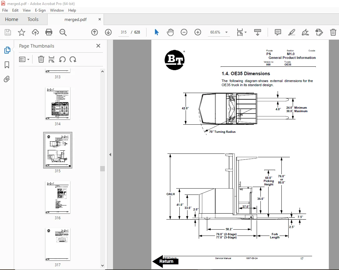
1 4 OE35 Dimensions 315
1 5 Data Plate 316
1 6 U L Construction Type 317
2 Main Components 318
Inch (SAE) and Metric Fasteners 321
1 Introduction 321
2 Nomenclature, Threads 322
3 Strength Identification 323
4 Conversion of Metric and English Units 329
Technical Service Data 331
Ordering Spare Parts 335
Introduction, Maintenance 337
1 Safe Jacking Procedure 337
Service Schedule 339
1 Planned Maintenance Schedule 339
Planned Maintenance Procedures 343
1 Services to be performed daily or at each 8 hour operating shift 343
1 1 Battery Discharge Indicator with slow down 343
1 2 Dash Display 343
1 3 Hydraulic System 344
1 4 Frame/Sheet Metal 344
1 5 Wheels/Tires 344
1 6 Functions/Operations 344
2 Services to be performed monthly or every 250 operating hours 345
2 1 Inspection 345
2 2 Transmission 345
2 3 Brakes 345
2 4 Battery 345
2 5 Electrical Connections 346
2 6 Contactor Tips (NOT Sealed) 346
2 7 Motor Brushes 346
2 8 Drive Motor 346
2 9 Hydraulic Reservoir 347
2 10 Frame Lube 347
2 11 Pivot Points 347
3 Services to be performed annually or every 1200 operating hours 348
3 1 Inspection 348
3 2 Transmission 348
3 3 Battery 348
3 4 Hydraulic System 349
3 5 Brakes 349
Lubrication Chart 351
Oil and Grease Specifications 353
1 Approved Oils and Grease 353
Contents, Section S 355
1 Service Instructions 355
Inspection Covers 357
1 Removal Of Plastic Dash Panel 358
Drive Motor 361
1 General Information 361
2 Operating Conditions 361
3 Troubleshooting 361
Drive Motor 24 Volt 367
1 Component Repair 368
2 Inspection and Troubleshooting 369
2 1 Drive End Head 369
2 2 Commutator End Head 369
2 3 Bearings 369
2 4 Brush and Commutator 370
2 5 Armature 370
2 6 Frame and Field Assembly 371
2 6 1 Testing 371
2 6 2 Frame and Field Service Notes 372
2 7 Assembly 373
2 7 1 Field Coil Installation 373
2 7 2 Bearing Installation 373
2 7 3 After Assembly 374
3 When changing brushes 374
Drive Motor 36 Volt 375
1 Component Repair 376
1 1 Disassembly 376
2 Inspection and Troubleshooting 377
2 1 Drive End Head 377
2 2 Commutator End Head 377
2 3 Bearings 377
2 4 Brush and Commutator 378
2 5 Armature 378
2 6 Frame and Field Assembly 379
2 6 1 Testing 379
2 6 2 Frame and Field Service Notes 380
2 7 Assembly 381
2 7 1 Field Coil Installation 381
2 7 2 Bearing Installation 381
2 7 3 After Assembly 382
3 When Changing Brushes 382
Transmission 383
1 System description 383
2 Troubleshooting 383
3 Removal 384
Transmission Disassembly / Assembly 387
4 Disassembly 388
5 Installation 395
Drive Wheel 397
5 1 Removal 397
5 2 Installation 398
Load Wheels 399
Stabilizing Caster Spring Loaded 401
1 Removal 402
2 Inspection 404
3 Disassembly 405
3 1 Installation 405
Torque Generator 407
1 Disassembly 409
2 Assembly 414
Steering System Pump 421
1 General Information 422
2 Removal 422
3 Installation 423
4 Disassembly 425
5 Inspection 426
6 Assembly 426
Steering System 429
1 General Information 429
Electrical System with TX and TT Card 431
1 Electrical Schematic Part 1 431
2 Electrical Schematic Part 2 432
3 Basics Of Circuit Operation 433
4 Control Features 435
4 1 Oscillator 435
4 2 Current Limit 436
4 3 Plugging 436
4 4 Pedal Position Plug 436
4 5 Ramp Start 437
4 6 Full Power Transition 437
4 7 Control Acceleration and 1A Time 437
4 8 1A Current Drop Out 437
4 9 Static Return to OFF 438
4 10 Accelerator Volts Hold-OFF 438
4 11 Coil Driver Modules 438
4 12 1A Thermal Hold-OFF 438
4 13 Must Pulse to Time 438
4 14 Pulse Monitor Trip (PMT) 439
4 15 Thermal Protector – (TP) 440
4 16 Low Voltage 440
4 17 Top Speed (Motor volts) Limit 440
4 18 Steer Pump Contactor Time Delay 440
4 19 Constant Current Coil Drivers and Internal Coil Suppression 441
4 20 Hourmeter Readings 441
4 21 Internal Resistance Compensation 441
4 22 Stored Status Code 441
4 23 On-board Diagnostics 441
4 24 Battery Discharge Indication 442
4 25 Handset 442
5 General Maintenance Instructions 443
6 Trouble-shooting Instructions 444
Battery Controller / Hourmeter / Lift Interrupt 447
1 General Information 447
2 Electrical 447
2 1 Voltage 447
2 1 1 The Contact Voltage and Current Ratings for Switching Resistive Loads 448
2 1 2 Memory Retention 448
3 Battery Controller (BC) 448
3 1 General Information 448
3 1 1 Discharge Adjustment 448
3 2 Reset 450
3 3 Key Switch 450
3 4 Hourmeter 451
4 Troubleshooting 451
4 1 Battery Discharge Indicator (BDI) 451
4 1 1 No Reset 451
4 1 2 Reset After Break in Power 451
4 1 3 No Discharge, Gauge Does Not Run Down 452
4 1 4 No Lockout 452
4 1 5 No Lift 452
4 1 6 Early Lockout 453
4 1 7 LEDs Do Not Light 453
4 2 Hourmeter 453
4 2 1 No Display 453
4 2 2 Hourmeter Glass Icon Does Not Flash 453
4 2 3 Hourmeter Glass Icon Always Flashes 454
Dash Display 455
1 General Information 455
2 Location 456
3 Operational Checks 456
3 1 Checking Hourmeter 456
3 2 Checking Battery Condition (BDI) 456
3 3 Checking Status Code (wrench) 456
4 Status Codes 457
EV100 LX Control Status Codes 459
SCR Component Checks 477
1 Main Logic Card 477
1 1 Instructions for Removal of Control Card 477
2 Capacitor 1C 478
3 Contactors Forward, Rearward, 1A, Power Steering, and Pump 478
4 Potentiometer in Accelerator 478
5 SCR’s (1REC, 2REC, 5REC) 478
6 Rectifiers (3REC, 4REC, Diode Blocks) 480
7 Thermal Protector (TP) 480
8 Filter Block (23FIL, etc ) 481
9 Filter Block (23FIL, etc ) 481
10 1X Choke and Reactor T3-T4 481
11 Replacement of EV100 Components 481
11 1 1REC, 2REC or 5REC 482
11 2 Capacitor 482
11 3 22REC, 23REC and 25REC 483
12 Instructions – EV100 Plugs 483
12 1 General 483
12 2 Procedures 483
12 3 Reference 484
Direction Contactor 485
1 General Information 486
2 Remove / replace contact tips 486
1A Speed Contactor 491
1 General Information 492
2 Disassembly 492
3 Assembly 494
Electrical System Troubleshooting 497
1 Control Circuits and Power Circuits 499
Electrical System Troubleshooting Charts 501
Pump Contactor 513
1 General Information 514
2 Disassembly 514
3 Assembly 516
Steering Pump Contactor 519
1 General Information 520
2 Disassembly 520
3 Assembly 522
EV100 Handset Operation 525
1 General Information 525
2 Purpose 526
3 Operation 527
4 Function Set-Up Procedures 528
5 Description and Location 530
6 Function Numbers for Controllers 531
6 1 Function 1 531
6 2 Function 2 531
6 3 Function 3 531
6 4 Function 4 532
6 5 Function 5 532
6 6 Function 6 532
6 7 Function 11 533
6 8 Function 12 533
6 9 Function 13 533
6 10 Function 14 534
6 11 Function 15 535
6 12 Function 16 535
6 13 Function 17 536
6 14 Function 18 537
Hydraulic System 539
1 Hydraulic Schematic 539
2 General Information 540
2 1 Lift/lower 540
2 2 Power Steering 541
2 3 Brake Release 541
3 Maintenance 542
4 Adjustments 542
Hydraulic Troubleshooting 543
1 Troubleshooting Chart 543
Lift Pump Assembly 547
1 Removal 548
2 Disassembly 549
3 Inspection 552
4 Assembly 554
Mast, 2 Stage 557
1 Shimming Mast on Truck 558
1 1 Shimming the Platform 558
1 2 Shimming the Rails 559
2 Two Stage Mast 562
2 1 Removal 562
2 2 Installation 563
2 3 Disassembly 564
2 4 Assembly 565
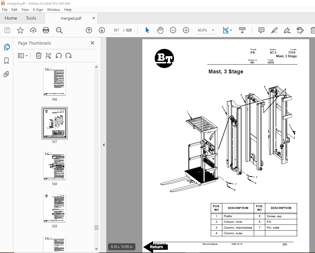
Mast, 3 Stage 567
1 Shimming Mast on Truck 568
1 1 Shimming the Platform 568
1 2 Shimming the Rails 569
2 Three Stage Mast 573
2 1 Removal 573
2 2 Installation 574
2 3 Disassembly 575
2 4 Assembly 576
Lift Cylinder, 2 Stage 579
1 Cylinder Repair 580
1 1 Removal 580
1 2 Disassembly 581
1 3 Assembly 581
1 4 Installation 581
Freelift Cylinder, 3 Stage 583
1 Freelift Cylinder Repair 584
1 1 Removal 584
1 2 Disassembly 585
1 3 Assembly 585
1 4 Installation 585
Staging Cylinder, 3 Stage 587
1 1 Removal 588
1 2 Disassembly 588
1 3 Assembly 588
1 4 Installation 589
Micro 70 Wire Guidance Important Information 591
1 Powering Up: 591
2 Powering Down: 591
Micro 70 Wire Guidance 593
1 Electrical Schematic Part 1 593
2 Electrical Schematic Part 2 594
3 Electrical Schematic Part 3 595
4 Electrical Schematic Part 4 596
5 Cautions and Warnings 597
6 Operation Information 599
6 1 Modes of operation 599
6 2 Acquiring the guide wire 599
6 3 Daily operational checks 602
7 Component Function and Relationship 603
8 Truck Set Up On Site 605
9 Troubleshooting Information 608
10 Troubleshooting Charts 611
Back Cover 628
S.V 04/02/2025