Trusted Business
Verified & Licensed
Virus Free Files
100% Safe Downloads
Secure Payment
SSL Protected
Instant Delivery
Available Immediately
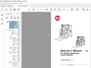
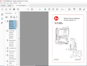
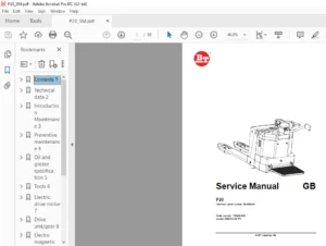
BT PRIME-MOVER OE-35 ELECTRIC ORDER SELECTOR REPAIR MANUAL 300116-000 – PDF DOWNLOAD
$24.95
BT PRIME-MOVER OE-35 ELECTRIC ORDER SELECTOR REPAIR MANUAL 300116-000 – PDF DOWNLOAD
Instant PDF Download
Available immediately
Save to Your Device
Download & keep forever
Antivirus Scanned
100% virus-free
Trusted Worldwide
175,000+ customers
Description
BT PRIME-MOVER OE-35 ELECTRIC ORDER SELECTOR REPAIR MANUAL 300116-000 – PDF DOWNLOAD
FILE DETAILS:
BT PRIME-MOVER OE-35 ELECTRIC ORDER SELECTOR REPAIR MANUAL 300116-000 – PDF DOWNLOAD
Language : English
Pages : 116
Downloadable : Yes
File Type : PDF
IMAGES PREVIEW OF THE MANUAL:
TABLE OF CONTENTS:
BT PRIME-MOVER OE-35 ELECTRIC ORDER SELECTOR REPAIR MANUAL 300116-000 – PDF DOWNLOAD
Front Cover...................................................  1
Index.........................................................  3
Specifications................................................  4
	1.0 Electrical, Amp Draws.................................  4
	2.0 Speeds................................................  4
	3.0 Hydraulics............................................  5
	4.0 Tires and Wheels......................................  5
	5.0 Fluids and Lubricants.................................  5
	6.0 SCR Card Trimpots.....................................  6
	7.0 Torque................................................  6
Lubrication Chart.............................................  7
Planned Maintenance Schedule..................................  8
Adjustments...................................................  9
	1.0 Brake.................................................  9
	3.0 Brake Interlock Switch................................  9
	5.0 Steering..............................................  9
	6.0 Lift Chains........................................... 10
	11.0 Speed Limiting Switch................................ 10
	12.0 SCR Card Trimpots.................................... 10
	18.0 Gate Switch.......................................... 10
	6.0 Lift Chains........................................... 11
	11.0 Speed Limiting Switch................................ 11
	12.0 SCR Card Trimpots.................................... 11
	18.0 Gate Switch.......................................... 11
	19.0 Potentiometer........................................ 11
Load Wheel Replacement........................................ 12
Drive Tire Replacement........................................ 13
Motor Service Instructions.................................... 14
	Cleaning.................................................. 14
	Visual Inspection......................................... 14
	Testing................................................... 14
	Armature.................................................. 15
	Frame and Field Service Notes............................. 15
	Field Coil Installation................................... 15
	Assembly and Testing...................................... 16
Electric Motor Repair......................................... 16
	Service Procedures........................................ 16
	Disassembly............................................... 16
	Cleaning.................................................. 18
	Visual Inspection......................................... 18
Motor Troubleshooting......................................... 20
Drive Motor Assembly.......................................... 21
Lift Motor Assembly........................................... 22
Steering Pump Motor Assembly.................................. 23
Electrical.................................................... 24
	2.0 Drive Motor........................................... 24
	3.0 Lift Motor............................................ 24
	4.0 Steering Motor........................................ 24
EV100 LX/LXT SCR Controls..................................... 25
	General Maintenance Instructions.......................... 27
	Troubleshooting Instructions.............................. 28
	Basics of Circuit Operation............................... 29
	Terminal Connections for LX/LXT........................... 35
	Troubleshooting Chart - Electrical........................ 37
		7.1 Dead Truck........................................ 37
		7.2 Lift.............................................. 38
		7.3 Steering.......................................... 39
		7.4 Travel............................................ 41
		7.5 Lowering.......................................... 42
	EV100 Handset............................................. 44
		General............................................... 44
		Purpose............................................... 44
		Operation............................................. 44
		Function Set-Up Procedures............................ 45
		Description of Function Numbers....................... 46
	Status Codes.............................................. 49
	Checking Components....................................... 69
	Replacement of EV100 Components........................... 74
	Instructions - EV100 Plugs................................ 75
		General............................................... 75
		Procedures............................................ 75
Hydraulic..................................................... 76
	1.0 Lift System Pump...................................... 76
	2.0 Steering System Pump.................................. 80
	5.0 Solenoid Valves....................................... 84
	6.0 Troubleshooting....................................... 85
Mast.......................................................... 91
	1.0 Shimming.............................................. 91
	2.0 Mast Removal, Installation, Disassembly & Assembly.... 97
Jacking and Hoisting..........................................105
Transmission..................................................106
	1.0 Removal...............................................106
	2.0 Disassembly and Repair................................106
	3.0 Installation..........................................113
Back Cover....................................................116
DESCRIPTION:
BT PRIME-MOVER OE-35 ELECTRIC ORDER SELECTOR REPAIR MANUAL 300116-000 – PDF DOWNLOAD
- The brake release cylinder should have 3/8″ to 1/2″ of travel. The cylinder travel itself is non-adjustable and the only brake adjustment is the aggressiveness adjusting screws on the side cover of the transmission case. Three allen head screws at the top of the transmission side cover adjust braking agressiveness.
- Loosen the locknuts and turn all three screws out of the transmission case until no force is felt pushing against any screw. Turn the screws back into the transmission case Just until spring resistance is felt. Now turn each screw an additional %” turn and tighten lock nut.
S.S 06/01/2025