BT Prime Mover MX65 RX65 Electric Low Lift Pallet Truck Parts Manual PDF
$28.95
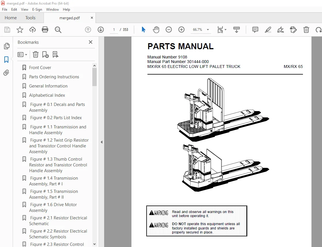
BT Prime Mover MX65 RX65 Electric Low Lift Pallet Truck Parts Manual – PDF DOWNLOAD
Description
BT Prime Mover MX65 RX65 Electric Low Lift Pallet Truck Parts Manual – PDF DOWNLOAD
FILE DETAILS:
BT Prime Mover MX65 RX65 Electric Low Lift Pallet Truck Parts Manual – PDF DOWNLOAD
Language : English
Pages : 353
Downloadable : Yes
File Type : PDF
IMAGES PREVIEW OF THE MANUAL:
TABLE OF CONTENTS:
BT Prime Mover MX65 RX65 Electric Low Lift Pallet Truck Parts Manual – PDF DOWNLOAD
Front Cover 1
Parts Ordering Instructions 2
General Information 3
Alphabetical Index 4
Figure # 0 1 Decals and Parts Assembly 6
Figure # 0 2 Parts List Index 8
Figure # 1 1 Transmission and Handle Assembly 10
Figure # 1 2 Twist Grip Resistor and Transistor Control Handle Assembly 12
Figure # 1 3 Thumb Control Resistor and Transistor Control Handle Assembly 14
Figure # 1 4 Transmission Assembly, Part # I 16
Figure # 1 5 Transmission Assembly, Part # II 18
Figure # 1 6 Drive Motor Assembly 20
Figure # 2 1 Resistor Electrical Schematic 22
Figure # 2 2 Resistor Electrical Schematic Symbols 23
Figure # 2 3 Resistor Control Wiring Harness Assembly 24
Figure # 2 5 Resistor Third Speed Power Component Wiring 26
Figure # 2 6 Resistor Control Panel Assembly 28
Figure # 2 7 Contactor Assembly 30
Figure # 2 8 Forward and Rearward Contactor Assembly 32
Figure # 2 9 Third Speed Contactor Panel Assembly 34
Figure # 2 10 Resistor Fourth Speed Control Wiring 36
Figure # 2 11 Resistor Fourth Speed Power Component Wiring 38
Figure # 2 12 Fourth Speed Contactor Panel Assembly 40
Figure # 2 13 Contactor Assembly 42
Figure # 2 14 Resistor Power Connector Assembly 44
Figure # 2 15 MX-65 Transistor Electrical Schematic 46
Figure # 2 16 MX-65 Transistor Electrical Schematic Symbols 47
Figure # 2 17 RX-65 Transistor Electrical Schematic 48
Figure # 2 18 RX-65 Transistor Electrical Schematic Symbols 49
Figure # 2 19 Transistor Control Wiring Harness Assembly 50
Figure # 2 20 Transistor Power Component Wiring 52
Figure # 2 21 Control Panel Assembly, 24 Volt 54
Figure # 2 22 Forward & Rearward Contactor Assembly, 24 Volt 56
Figure # 2 23 High Speed Contactor Assembly, 24 Volt 58
Figure # 2 24 Transistor Power Connector Assembly 60
Figure # 2 25 Hydraulic Pump Motor Assembly 62
Figure # 2 26 MX-65, 12 Volt Drive Motor Assembly 64
Figure # 2 27 MX-65, 24 Volt Drive Motor Assembly 66
Figure # 2 28 RX-65, 12 Volt Drive Motor Assembly 68
Figure # 2 29 RX-65, 24 Volt Drive Motor Assembly 70
Figure # 3 1 Hydraulic Schematic 72
Figure # 3 2 Hydraulic Schematic Symbols 73
Figure # 3 3 Resistor Hydraulic System 74
Figure # 3 4 Transistor Hydraulic System 76
Figure # 3 5 Pump and Motor Assembly 78
Figure # 3 6 Lift Cylinder Assembly 80
Figure # 4 1 Shielding Assembly 82
Figure # 4 2 Carrier Frame Assembly 84
Figure # 4 3 Caster Assembly 86
Figure # 4 4 HX-65 Lift Frame Assembly 88
Figure # 4 5 Pallet Entry Rollers 90
Figure # 4 6 Skid Adapter and Package Guard Assembly 92
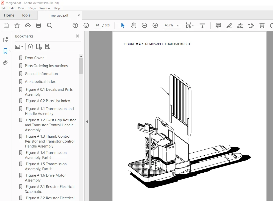
Figure # 4 7 Removable Load Backrest 94
Figure # 7 1 Special Tools and Lubrications 96
Front Cover 98
Parts Ordering Instructions 99
Field Modifications 99
General Information 100
Alphabetical Index 101
Figure # 0 1 Decals and Parts Assembly 103
Figure # 0 2 Parts List Index 105
Figure # 1 1 Transmission and Handle Assembly 107
Figure # 1 2 Twist Grip Resistor & Transistor Control Handle Assembly 109
Figure # 1 3 Thumb Control Resistor & Transistor Control Handle Assembly 111
Figure # 1 4 Transmission Assembly, Part # 1 113
Figure # 1 5 Transmission Assembly, Part # 2 115
Figure # 1 6 Drive Motor Assembly 117
Figure # 2 1 MX/RX 2 & 3 Speed Resistor Electrical Schematic 119
Figure # 2 2 MX/RX 2 & 3 Speed Resistor Electrical Schematic Symbols 120
Figure # 2 3 MX/RX 2 & 3 Speed Resistor Control Wiring Harness Assembly 121
Figure # 2 4 MX/RX 2 & 3 Speed Resistor Control Wiring 123
Figure # 2 5 MX/RX 2 & 3 Speed Resistor Power Component Wiring 125
Figure # 2 6 MX/RX 2 Speed Resistor Control Panel Assembly 127
Figure # 2 7 MX/RX 2 & 3 Speed Second Speed Contactor Assembly 129
Figure # 2 8 MX/RX 2 & 3 Speed Forward & Rearward Contactor Assembly 131
Figure # 2 9 RX 3 Speed Third Speed Contactor Panel Assembly 133
Figure # 2 10 MX/RX 2 & 3 Speed Resistor Contactor Assembly 135
Figure # 2 11 MX/RX 3 Speed Walkie/4 Speed Rider Resistor Electrical Schematic 137
Figure # 2 12 Resistor Electrical Schematic Symbols 138
Figure # 2 13 MX 3 Speed Walkie Resistor Control Wiring Harness Assembly 139
Figure # 2 14 MX 3 Speed Walkie Resistor Third Speed Control Wiring 141
Figure # 2 15 MX 3 Speed Walkie Resistor Third Speed Power Component Wiring 143
Figure # 2 16 MX 3 Speed Walkie Third Speed Contactor Panel Assembly 145
Figure # 2 17 RX 4 Speed Resistor Fourth Speed Control Wiring 147
Figure # 2 18 RX 4 Speed Resistor Fourth Speed Power Component Wiring 149
Figure # 2 19 MX/RX 3 Speed Walkie/4 Speed Rider Resistor Control Panel Assy 151
Figure # 2 20 MX/RX 3 & 4 Speed Second Speed Contactor Assembly 153
Figure # 2 21 MX/RX 3 & 4 Speed Forward & Rearward Contactor Assembly 155
Figure # 2 22 RX 4 Speed Fourth Speed Contactor Panel Assembly 157
Figure # 2 23 RX 4 Speed Fourth Speed Contactor Assembly 159
Figure # 2 24 MX/RX Resistor Power Connector Assembly 161
Figure # 2 25 MX-65 Transistor Electrical Schematic 163
Figure # 2 26 MX-65 Transistor Electrical Schematic Symbols 164
Figure # 2 27 RX-65 Transistor Electrical Schematic 165
Figure # 2 28 RX-65 Transistor Electrical Schematic Symbols 166
Figure # 2 29 Transistor Control Wiring Harness Assembly 167
Figure # 2 30 Transistor Power Component Wiring 169
Figure # 2 31 Transistor Control Panel Assembly, 24 Volt 171
Figure # 2 32 Forward & Rearward Contactor Assembly 173
Figure # 2 33 High Speed Contactor Assembly 175
Figure # 2 34 Transistor Power Connector Assembly 177
Figure # 2 35 Pump Motor Assembly 179
Figure # 2 36 MX/RX-65, 12 Volt Drive Motor Assembly 181
Figure # 2 37 MX-65, 24 Volt Drive Motor Assembly 183
Figure # 2 38 RX-65, 24 Volt Drive Motor Assembly 185
Figure # 3 1 Hydraulic Schematic 187
Figure # 3 2 Hydraulic Schematic Symbols 188
Figure # 3 3 Resistor Hydraulic System 189
Figure # 3 4 Transistor Hydraulic System 191
Figure # 3 5 Pump and Motor Assembly 193
Figure # 3 6 Lift Cylinder Assembly 195
Figure # 4 1 Shielding Assembly 197
Figure # 4 2 Carrier Frame Assembly 199
Figure # 4 3 Caster Assembly 201
Figure # 4 4 Lift Frame Assembly 203
Figure # 4 5 Pallet Entry Rollers 205
Figure # 4 6 Skid Adapter and Package Guard Assembly 207
Figure # 4 7 Removable Load Backrest 209
Figure # 10 1 Special Tools and Lubrications 211
Numerical Index 214
Front Cover 226
Pars Ordering Instructions 227
General Information 228
Alphabetical Index 229
Section 0 0 231
Figure # 0 1 231
Figure # 0 2 233
Section 1 0 235
Figure # 1 1 235
Figure # 1 2 237
Figure # 1 3 239
Figure # 1 4 241
Figure # 1 5 243
Figure # 1 6 245
Section 2 0 247
Figure # 2 1 247
Figure # 2 2 248
Figure # 2 3 249
Figure # 2 4 251
Figure # 2 5 253
Figure # 2 6 255
Figure # 2 7 257
Figure # 2 8 259
Figure # 2 9 261
Figure # 2 10 263
Figure # 2 11 265
Figure # 2 12 266
Figure # 2 13 267
Figure # 2 14 269
Figure # 2 15 271
Figure # 2 16 273
Figure # 2 17 275
Figure # 2 18 277
Figure # 2 19 279
Figure # 2 20 281
Figure # 2 21 283
Figure # 2 22 285
Figure # 2 23 287
Figure # 2 24 289
Figure # 2 25 291
Figure # 2 26 292
Figure # 2 27 293
Figure # 2 28 294
Figure # 2 29 295
Figure # 2 30 297
Figure # 2 31 299
Figure # 2 32 301
Figure # 2 33 303
Figure # 2 34 305
Figure # 2 35 307
Figure # 2 36 309
Figure # 2 37 311
Figure # 2 38 313
Section 3 0 315
Figure # 3 1 315
Figure # 3 2 316
Figure # 3 3 317
Figure # 3 4 319
Figure # 3 5 321
Figure # 3 6 323
Section 4 0 325
Figure # 4 1 325
Figure # 4 2 327
Figure # 4 3 329
Figure # 4 4 331
Figure # 4 5 333
Figure # 4 6 335
Figure # 4 7 337
Section 10 0 339
Figure # 10 1 339
Numerical Index 342
DESCRIPTION:
BT Prime Mover MX65 RX65 Electric Low Lift Pallet Truck Parts Manual – PDF DOWNLOAD
Manual Number 9108
Manual Part Number 301444-000
PARTS ORDERING INSTRUCTIONS:
HOW TO ORDER:
- When you order, supply the part number, quantity, model and serial numbers of your machine. Supplying this information will assure prompt, efficient handling of your order. The pictorial reference number is not needed and including it can only add confusion.
- Since your dealer carries many parts in stock and maintains up-to-date prices on all parts, he will be able to process your order immediately. If, for some reason, the part is not in stock, he will order it from the factory. In either event, he maintains a current file of service manuals, which give all available parts ordering or technical information.
- All prices are FOB factory in Muscatine, Iowa. Shipping charges are added to the price of the part shipping from the factory.
WHERE TO ORDER
Always order parts from the dealer who sold you your BT PRIME-MOVER. If it is necessary for the dealer to order parts from the factory, he is able to get prompt service for you. Parts are shipped in accordance with shipping instructions given on the order.
S.V 20/01/2025