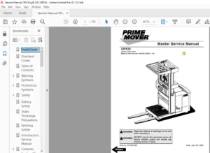
BT Prime-Mover MX50 RX50 Electric Low Lift Pallet Truck Parts Manual PDF
$28.95
BT Prime-Mover MX50 RX50 Electric Low Lift Pallet Truck Parts Manual – PDF DOWNLOAD
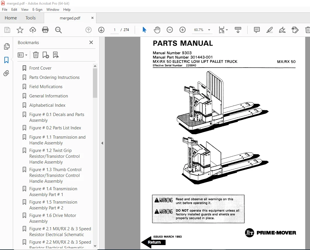
Manual Number 9303
Manual Part Number 301443-001
Effective Serial Number 226840
Description
BT Prime-Mover MX50 RX50 Electric Low Lift Pallet Truck Parts Manual – PDF DOWNLOAD
FILE DETAILS:
BT Prime-Mover MX50 RX50 Electric Low Lift Pallet Truck Parts Manual – PDF DOWNLOAD
Language : English
Pages : 274
Downloadable : Yes
File Type : PDF
IMAGES PREVIEW OF THE MANUAL:
TABLE OF CONTENTS:
BT Prime-Mover MX50 RX50 Electric Low Lift Pallet Truck Parts Manual – PDF DOWNLOAD
Manual Number 9303
Manual Part Number 301443-001
Effective Serial Number 226840
Front Cover 1
Parts Ordering Instructions 2
Field Mofications 2
General Information 3
Alphabetical Index 4
Figure # 0 1 Decals and Parts Assembly 6
Figure # 0 2 Parts List Index 8
Figure # 1 1 Transmission and Handle Assembly 10
Figure # 1 2 Twist Grip Resistor/Transistor Control Handle Assembly 12
Figure # 1 3 Thumb Control Resistor/Transistor Control Handle Assembly 14
Figure # 1 4 Transmission Assembly Part # 1 16
Figure # 1 5 Transmission Assembly Part # 2 18
Figure # 1 6 Drive Motor Assembly 20
Figure # 2 1 MX/RX 2 & 3 Speed Resistor Electrical Schematic 22
Figure # 2 2 MX/RX 2 & 3 Speed Resistor Electrical Schematic Symbols 23
Figure # 2 3 MX/RX 2 & 3 Speed Resistor Control Wiring Harness Assembly 24
Figure # 2 4 MX/RX 2 & 3 Speed Resistor Control Wiring 26
Figure # 2 5 MX/RX 2 & 3 Speed Resistor Power Component Wiring 28
Figure # 2 6 MX/RX 2 Speed Resistor Control Panel Assembly 30
Figure # 2 7 MX/RX 2 & 3 Speed Second Speed Contactor Assembly 32
Figure # 2 8 MX/RX 2 & 3 Speed Forward & Rearward Contactor Assembly 34
Figure # 2 9 RX 3 Speed Third Speed Contactor Panel Assembly 36
Figure # 2 10 MX/RX 2 & 3 Speed Resistor Contactor Assembly 38
Figure # 2 11 MX/RX 3 Speed Walkie/4 Speed Rider Resistor Electrical Schematic 40
Figure # 2 12 Resistor Electrical Schematic Symbols 41
Figure # 2 13 MX 3 Speed Walkie Resistor Control Wiring Harness Assembly 42
Figure # 2 14 MX 3 Speed Walkie Resistor Third Speed Control Wiring 44
Figure # 2 15 MX 3 Speed Walkie Resistor Third Speed Power Component Wiring 46
Figure # 2 16 MX 3 Speed Walkie Third Speed Contactor Panel Assembly 48
Figure # 2 17 RX 4 Speed Resistor Fourth Speed Control Wiring 50
Figure # 2 18 RX 4 Speed Resistor Fourth Speed Power Component Wiring 52
Figure # 2 19 MX/RX 3 Speed Walkie/4 Speed Rider Resistor Control Panel Assembly 54
Figure # 2 20 MX/RX 3 & 4 Speed Second Speed Contactor Assembly 56
Figure # 2 21 MX/RX 3 & 4 Speed Forward & Rearward Contactor Assembly 58
Figure # 2 22 RX 4 Speed Fourth Speed Contactor Panel Assembly 60
Figure # 2 23 RX 4 Speed Fourth Speed Contactor Assembly 62
Figure # 2 24 MX/RX Resistor Power Connector Assembly 64
Figure # 2 25 MX-50 Transistor Electrical Schematic 66
Figure # 2 26 MX-50 Transistor Electrical Schematic Symbols 67
Figure # 2 27 RX-50 Transistor Electrical Schematic 68
Figure # 2 28 RX-50 Transistor Electrical Schematic Symbols 69
Figure # 2 29 Transistor Control Wiring Harness Assembly 70
Figure # 2 30 Transistor Power Component Wiring 72
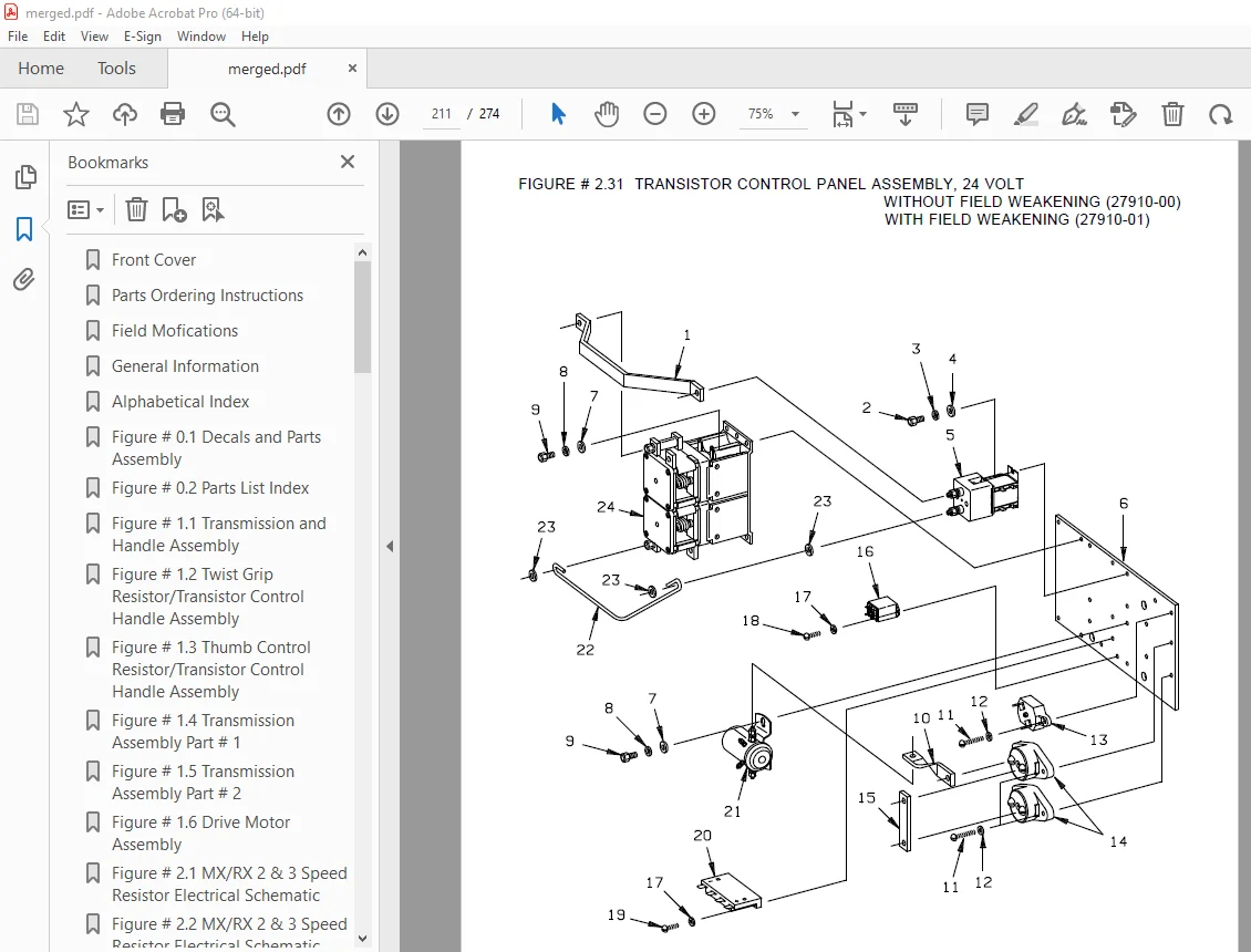
Figure # 2 31 Transistor Control Panel Assembly, 24 Volt 74
Figure # 2 32 Forward & Rearward Contactor Assembly 76
Figure # 2 33 High Speed Contactor Assembly 78
Figure # 2 34 Transistor Power Connector Assembly 80
Figure # 2 35 Pump Motor Assembly 82
Figure # 2 36 MX/RX-50, 12 Volt Drive Motor Assembly 84
Figure # 2 37 MX-50, 24 Volt Drive Motor Assembly 86
Figure # 2 38 RX-50, 24 Volt Drive Motor Assembly 88
Figure # 3 1 Hydraulic Schematic 90
Figure # 3 2 Hydraulic Schematic Symbols 91
Figure # 3 3 Resistor Hydraulic System 92
Figure # 3 4 Transistor Hydraulic System 94
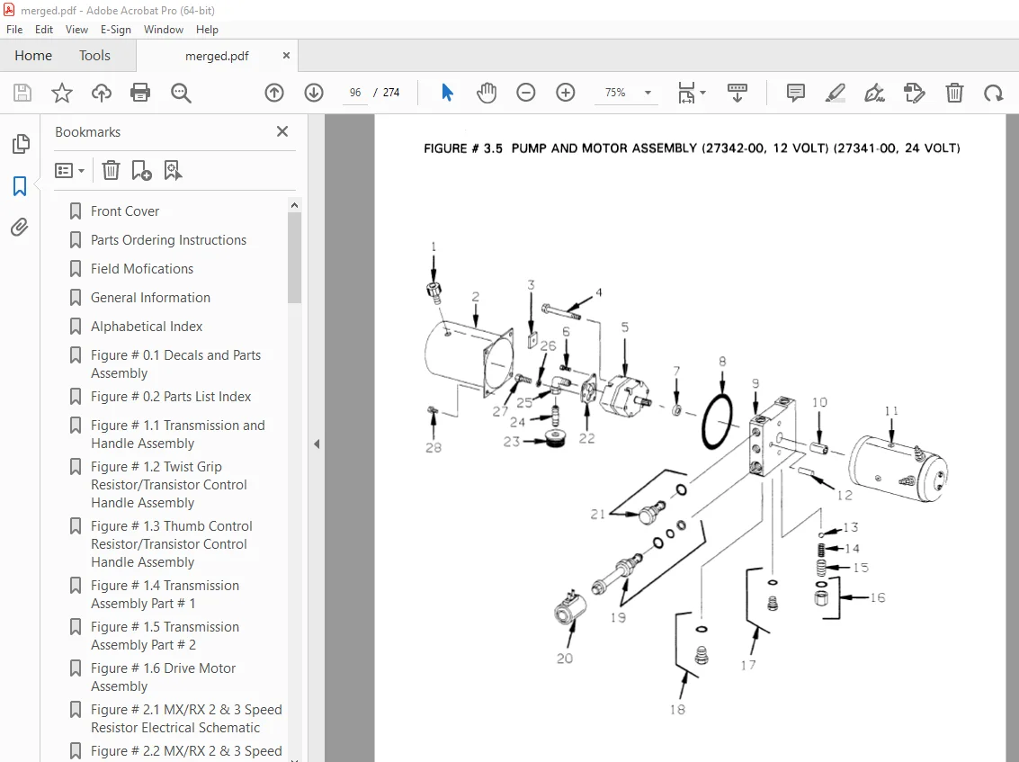
Figure # 3 5 Pump and Motor Assembly 96
Figure # 3 6 Lift Cylinder Assembly 98
Figure # 4 1 Shielding Assembly 100
Figure # 4 2 Carrier Frame Assembly 102
Figure # 4 3 Caster Assembly 104
Figure # 4 4 Lift Frame Assembly 106
Figure # 4 5 Pallet Entry Rollers 110
Figure # 4 6 Skid Adapter and Package Guard Assembly 112
Figure # 4 7 Removable Load Backrest 114
Figure # 5 1 Battery Pack 116
Figure # 5 2 Battery Pack Cable Assembly 118
Figure # 5 3 Battery Pack Connector Assembly 120
Figure # 10 1 Special Tools and Lubrications 122
Numerical Index 125
Front Cover 138
Parts Ordering Instructions 139
General Information 140
Alphabetical Index 141
Section 0 0 143
Figure # 0 1 143
Figure # 0 2 145
Section 1 0 147
Figure # 1 1 147
Figure # 1 2 149
Figure # 1 3 151
Figure # 1 4 153
Figure # 1 5 155
Figure # 1 6 157
Section 2 0 159
Figure # 2 1 159
Figure # 2 2 160
Figure # 2 3 161
Figure # 2 4 163
Figure # 2 5 165
Figure # 2 6 167
Figure # 2 7 169
Figure # 2 8 171
Figure # 2 9 173
Figure # 2 10 175
Figure # 2 11 177
Figure # 2 12 178
Figure # 2 13 179
Figure # 2 14 181
Figure # 2 15 183
Figure # 2 16 185
Figure # 2 17 187
Figure # 2 18 189
Figure # 2 19 191
Figure # 2 20 193
Figure # 2 21 195
Figure # 2 22 197
Figure # 2 23 199
Figure # 2 24 201
Figure # 2 25 203
Figure # 2 26 204
Figure # 2 27 205
Figure # 2 28 206
Figure # 2 29 207
Figure # 2 30 209
Figure # 2 31 211
Figure # 2 32 213
Figure # 2 33 215
Figure # 2 34 217
Figure # 2 35 219
Figure # 2 36 221
Figure # 2 37 223
Figure # 2 38 225
Section 3 0 227
Figure # 3 1 227
Figure # 3 2 228
Figure # 3 3 229
Figure # 3 4 231
Figure # 3 5 233
Figure # 3 6 235
Section 4 0 237
Figure # 4 1 237
Figure # 4 2 239
Figure # 4 3 241
Figure # 4 4 243
Figure # 4 5 247
Figure # 4 6 249
Figure # 4 7 251
Section 5 0 253
Figure # 5 1 253
Figure # 5 2 255
Figure # 5 3 257
Section 10 0 259
Figure # 10 1 259
Numerical Index 262
DESCRIPTION:
BT Prime-Mover MX50 RX50 Electric Low Lift Pallet Truck Parts Manual – PDF DOWNLOAD
Manual Number 9303
Manual Part Number 301443-001
Effective Serial Number 226840
PARTS ORDERING INSTRUCTIONS:
HOW TO ORDER:
- When you order, supply the part number, quantity, model and serial numbers of your machine. Supplying this information will assure prompt, efficient handling of your order. The pictorial reference number is not needed and including it can only add confusion.
- Since your dealer carries many parts in stock and maintains up-to-date prices on all parts, he will be able to process your order immediately. If, for some reason, the part is not in stock, he will order it from the factory. In either event, he maintains a current file of service manuals, which give all available parts ordering or technical information.
- All prices are FOB factory in Muscatine, Iowa. Shipping charges are added to the price of the part shipping from the factory.
WHERE TO ORDER
Always order parts from the dealer who sold you your BT PRIME-MOVER. If it is necessary for the dealer to order parts from the factory, he is able to get prompt service for you. Parts are shipped in accordance with shipping instructions given on the order.
S.V 21/01/2025