BT PRIME MOVER HMX/RMX PARTS MANUAL – PDF DOWNLOAD
$41.95
BT PRIME MOVER HMX/RMX PARTS MANUAL – PDF DOWNLOAD
302064-000 1994_February
302064-001 1994_April
302064-002 1994_September
302064-003 1994_November
302064-004 1995_January
302064-005 1995_June
302064-006 1995_September
302064-007 1995_December
302064-008 1996_December
302064-008 1997_May
302064-008 1997_December
302064-008 1998_September
302064-008 1999_October
302064-009 2001_August
302064-010 2002_February
304002-000 1994_November Designed and built for C&S Grocery Store
306753-000 1996_October Addendum, HMX-50 Designed and built for U.S.A Post Office
Description
BT PRIME MOVER HMX/RMX PARTS MANUAL – PDF DOWNLOAD
FILE DETAILS:
BT PRIME MOVER HMX/RMX PARTS MANUAL – PDF DOWNLOAD
Language : English
Pages : 1840
Downloadable : Yes
File Type : PDF
302064-000 1994_February
302064-001 1994_April
302064-002 1994_September
302064-003 1994_November
302064-004 1995_January
302064-005 1995_June
302064-006 1995_September
302064-007 1995_December
302064-008 1996_December
302064-008 1997_May
302064-008 1997_December
302064-008 1998_September
302064-008 1999_October
302064-009 2001_August
302064-010 2002_February
304002-000 1994_November Designed and built for C&S Grocery Store
306753-000 1996_October Addendum, HMX-50 Designed and built for U.S.A Post Office
IMAGES PREVIEW OF THE MANUAL:
TABLE OF CONTENTS:
BT PRIME MOVER HMX/RMX PARTS MANUAL – PDF DOWNLOAD
HMX_RMX Parts Welcome.............................................................................. 1
302064-000 1994_February........................................................................... 2
Front Cover.................................................................................... 2
Parts Ordering Instructions.................................................................... 3
General Information............................................................................ 4
Alphabetical Index............................................................................. 5
Section 0.0.................................................................................... 7
Figure # 0.1............................................................................... 7
Section 1.0.................................................................................... 9
Figure # 1.1............................................................................... 9
Figure # 1.2............................................................................... 11
Figure # 1.3............................................................................... 13
Section 2.0.................................................................................... 15
Figure # 2.1............................................................................... 15
Figure # 2.2............................................................................... 16
Figure # 2.3............................................................................... 17
Figure # 2.4............................................................................... 19
Figure # 2.5............................................................................... 21
Figure # 2.6............................................................................... 23
Figure # 2.7............................................................................... 24
Figure # 2.8............................................................................... 25
Figure # 2.9............................................................................... 27
Figure # 2.10.............................................................................. 29
Figure # 2.11.............................................................................. 30
Figure # 2.12.............................................................................. 31
Figure # 2.13.............................................................................. 33
Figure # 2.14.............................................................................. 35
Figure # 2.15.............................................................................. 37
Figure # 2.16.............................................................................. 39
Figure # 2.17.............................................................................. 41
Figure # 2.18.............................................................................. 43
Figure # 2.19.............................................................................. 45
Figure # 2.20.............................................................................. 47
Section 3.0.................................................................................... 49
Figure # 3.1............................................................................... 49
Figure # 3.2............................................................................... 50
Figure # 3.3............................................................................... 51
Figure # 3.4............................................................................... 53
Section 4.0.................................................................................... 55
Figure # 4.1............................................................................... 55
Figure # 4.2............................................................................... 57
Figure # 4.3............................................................................... 59
Figure # 4.4............................................................................... 61
Figure # 4.5............................................................................... 63
Figure # 4.6............................................................................... 65
Figure # 4.7............................................................................... 67
Figure # 4.8............................................................................... 69
Figure # 4.9............................................................................... 71
Section 10.0................................................................................... 73
Figure # 10.1.............................................................................. 73
Numberical Index............................................................................... 76
Back Cover..................................................................................... 85
302064-001 1994_April.............................................................................. 86
Front Cover.................................................................................... 86
Parts Ordering Instructions.................................................................... 87
General Information............................................................................ 88
Alphabetical Index............................................................................. 89
Section 0.0.................................................................................... 91
Figure # 0.1............................................................................... 91
Section 1.0.................................................................................... 93
Figure # 1.1............................................................................... 93
Figure # 1.2............................................................................... 95
Figure # 1.3............................................................................... 97
Section 2.0.................................................................................... 99
Figure # 2.1............................................................................... 99
Figure # 2.2............................................................................... 100
Figure # 2.3............................................................................... 101
Figure # 2.4............................................................................... 103
Figure # 2.5............................................................................... 105
Figure # 2.6............................................................................... 107
Figure # 2.7............................................................................... 108
Figure # 2.8............................................................................... 109
Figure # 2.9............................................................................... 111
Figure # 2.10.............................................................................. 113
Figure # 2.11.............................................................................. 114
Figure # 2.12.............................................................................. 115
Figure # 2.13.............................................................................. 117
Figure # 2.14.............................................................................. 119
Figure # 2.15.............................................................................. 121
Figure # 2.16.............................................................................. 123
Figure # 2.17.............................................................................. 125
Figure # 2.18.............................................................................. 127
Figure # 2.19.............................................................................. 129
Figure # 2.20.............................................................................. 131
Section 3.0.................................................................................... 133
Figure # 3.1............................................................................... 133
Figure # 3.2............................................................................... 134
Figure # 3.3............................................................................... 135
Figure # 3.4............................................................................... 137
Section 4.0.................................................................................... 139
Figure # 4.1............................................................................... 139
Figure # 4.2............................................................................... 141
Figure # 4.3............................................................................... 143
Figure # 4.4............................................................................... 145
Figure # 4.5............................................................................... 147
Figure # 4.6............................................................................... 149
Figure # 4.7............................................................................... 151
Figure # 4.8............................................................................... 153
Figure # 4.9............................................................................... 155
Section 10.0................................................................................... 157
Figure # 10.1.............................................................................. 157
Back Cover..................................................................................... 159
302064-002 1994_September.......................................................................... 160
Front Cover.................................................................................... 160
Parts Ordering Instructions.................................................................... 161
General Information............................................................................ 162
Alphabetical Index............................................................................. 163
Section 0.0.................................................................................... 165
Figure # 0.1 Decals and Parts List Assembly................................................ 165
Section 1.0.................................................................................... 167
Figure # 1.1 Handle and Transmission Installation.......................................... 167
Figure # 1.2 Control Handle Head Assembly.................................................. 169
Figure # 1.3 Transmission Assembly......................................................... 171
Section 2.0.................................................................................... 173
Figure # 2.1 RMX 12 Volt Electrical Schematic.............................................. 173
Figure # 2.2 RMX 12 Volt Electrical Schematic Symbols...................................... 174
Figure # 2.3 RMX 12 Volt Electrical Assembly............................................... 175
Figure # 2.4 RMX 12 Volt Electrical Panel Assembly......................................... 177
Figure # 2.5 12 & 24 Volt Forward & Rearward Contactor Assembly............................ 179
Figure # 2.6 RMX 24 Volt Electrical Schematic.............................................. 181
Figure # 2.7 RMX 24 Volt Electrical Schematic Symbols...................................... 182
Figure # 2.8 RMX 24 Volt Electrical Assembly............................................... 183
Figure # 2.9 RMX 24 Volt Electrical Panel Assembly......................................... 185
Figure # 2.10 HMX 24 Volt Electrical Schematic............................................. 187
Figure # 2.11 HMX 24 Volt Electrical Schematic Symbols..................................... 188
Figure # 2.12 HMX 24 Volt Electrical Assembly.............................................. 189
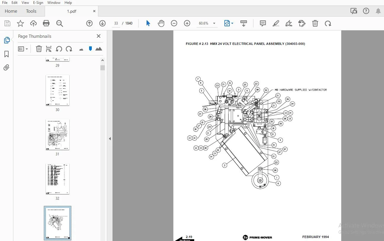
Figure # 2.13 HMX 24 Volt Electrical Panel Assembly........................................ 191
Figure # 2.14 HMX 24 Volt 1A Contactor Assembly............................................ 193
Figure # 2.15 12/24 Volt Electrical Lift Interrupt......................................... 195
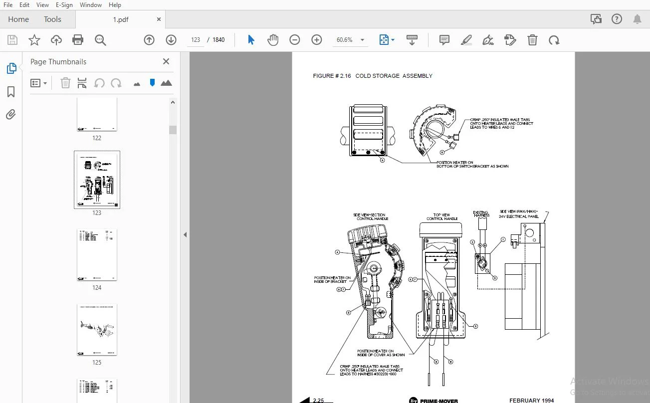
Figure # 2.16 Cold Storage Assembly........................................................ 197
Figure # 2.17 Pump Motor Assembly.......................................................... 199
Figure # 2.18 RMX 12 Volt Drive Motor Assembly............................................. 201
Figure # 2.19 RMX/HMX 24 Volt Drive Motor Assembly......................................... 203
Figure # 2.20 HMX 24 Volt Drive Motor Assembly............................................. 205
Section 3.0.................................................................................... 207
Figure # 3.1 Hydraulic Schematic........................................................... 207
Figure # 3.2 Hydraulic Schematic Symbols................................................... 208
Figure # 3.3 Hydraulic System Assembly..................................................... 209
Figure # 3.4 Hydraulic Pump and Motor...................................................... 211
Section 4.0.................................................................................... 213
Figure # 4.1 Frame Assembly................................................................ 213
Figure # 4.2 RMX Spring Loaded Caster Assembly............................................. 217
Figure # 4.3 Load Wheel Assembly........................................................... 219
Figure # 4.4 HMX Hand Rail Assembly........................................................ 221
Figure # 4.5 HMX Caster Torsion Rod Assembly............................................... 223
Figure # 4.6 HMX Caster Assembly........................................................... 225
Figure # 4.7 Battery Rollers and Frame Assembly............................................ 227
Figure # 4.8 Pallet Entry Rollers.......................................................... 229
Figure # 4.9 Removable Load Backrest....................................................... 231
Figure # 4.10 Shields and Guards........................................................... 233
Section 10.0................................................................................... 235
Figure # 10.1 Special Tools and Lubrications............................................... 235
Numerical Index................................................................................ 238
Back Cover..................................................................................... 247
302064-003 1994_November........................................................................... 248
Front Cover.................................................................................... 248
Parts Ordering Instructions.................................................................... 249
General Information............................................................................ 250
Alphabetical Index............................................................................. 251
Section 0.0.................................................................................... 253
Figure # 0.1............................................................................... 253
Section 1.0.................................................................................... 255
Figure # 1.1............................................................................... 255
Figure # 1.2............................................................................... 257
Figure # 1.3............................................................................... 259
Figure # 1.4............................................................................... 261
Section 2.0.................................................................................... 263
Figure # 2.1............................................................................... 263
Figure # 2.2............................................................................... 264
Figure # 2.3............................................................................... 265
Figure # 2.4............................................................................... 267
Figure # 2.5............................................................................... 269
Figure # 2.6............................................................................... 271
Figure # 2.7............................................................................... 272
Figure # 2.8............................................................................... 273
Figure # 2.9............................................................................... 275
Figure # 2.10.............................................................................. 277
Figure # 2.11.............................................................................. 278
Figure # 2.12.............................................................................. 279
Figure # 2.13.............................................................................. 281
Figure # 2.14.............................................................................. 283
Figure # 2.15.............................................................................. 285
Figure # 2.16.............................................................................. 287
Figure # 2.17.............................................................................. 289
Figure # 2.18.............................................................................. 291
Figure # 2.19.............................................................................. 293
Section 3.0.................................................................................... 295
Figure # 3.1............................................................................... 295
Figure # 3.2............................................................................... 296
Figure # 3.3............................................................................... 297
Figure # 3.4............................................................................... 299
Section 4.0.................................................................................... 301
Figure # 4.1............................................................................... 301
Figure # 4.2............................................................................... 305
Figure # 4.3............................................................................... 307
Figure # 4.4............................................................................... 309
Figure # 4.5............................................................................... 311
Figure # 4.6............................................................................... 313
Figure # 4.7............................................................................... 315
Figure # 4.8............................................................................... 317
Figure # 4.9............................................................................... 319
Figure # 4.10.............................................................................. 321
Figure # 4.11.............................................................................. 323
Section 10.0................................................................................... 325
Figure # 10.1.............................................................................. 325
Numerical Index................................................................................ 328
Back Cover..................................................................................... 337
302064-004 1995_January............................................................................ 338
Front Cover.................................................................................... 338
Parts Ordering Instructions.................................................................... 339
General Information............................................................................ 340
Alphabetical Index............................................................................. 341
Section 0.0.................................................................................... 343
Figure # 0.1 Decals and Parts List Assembly................................................ 343
Section 1.0.................................................................................... 345
Figure # 1.1 Handle and Transmission Installation.......................................... 345
Figure # 1.2 Control Handle Head Assembly.................................................. 347
Figure # 1.3 Walk Along Knob Control Handle Head Assembly.................................. 349
Figure # 1.4 Transmission Assembly......................................................... 351
Section 2.0.................................................................................... 353
Figure # 2.1 RMX 12 Volt Electrical Schematic.............................................. 353
Figure # 2.2 RMX 12 Volt Electrical Schematic Symbols...................................... 354
Figure # 2.3 RMX 12 Volt Electrical Assembly............................................... 355
Figure # 2.4 RMX 12 Volt Electrical Panel Assembly......................................... 357
Figure # 2.5 12 & 24 Volt Forward & Rearward Contactor Assembly............................ 359
Figure # 2.6 RMX 24 Volt Electrical Schematic.............................................. 361
Figure # 2.7 RMX 24 Volt Electrical Schematic Symbols...................................... 362
Figure # 2.8 RMX 24 Volt Electrical Assembly............................................... 363
Figure # 2.9 RMX 24 Volt Electrical Panel Assembly......................................... 365
Figure # 2.10 HMX 24 Volt Electrical Schematic............................................. 367
Figure # 2.11 HMX 24 Volt Electrical Schematic Symbols..................................... 368
Figure # 2.12 HMX 24 Volt Electrical Assembly.............................................. 369
Figure # 2.13 HMX 24 Volt Electrical Panel Assembly........................................ 371
Figure # 2.14 HMX 24 Volt 1A Contactor Assembly............................................ 373
Figure # 2.15 12/24 Volt Electrical Lift Interrupt......................................... 375
Figure # 2.16 Cold Storage Assembly........................................................ 377
Figure # 2.17 Pump Motor Assembly.......................................................... 379
Figure # 2.18 RMX 12 Volt Drive Motor Assembly............................................. 381
Figure # 2.19 RMX/HMX 24 Volt Drive Motor Assembly......................................... 383
Section 3.0.................................................................................... 385
Figure # 3.1 Lift Hydraulic Schematic...................................................... 385
Figure # 3.2 Hydraulic Schematic Symbols................................................... 386
Figure # 3.3 Hydraulic System Assembly..................................................... 387
Figure # 3.4 Hydraulic Pump and Motor Assembly............................................. 389
Section 4.0.................................................................................... 391
Figure # 4.1 Frame Assembly................................................................ 391
Figure # 4.2 RMX Spring Loaded Caster Assembly............................................. 395
Figure # 4.3 Load Wheel Assembly........................................................... 397
Figure # 4.4 HMX Hand Rail Assembly........................................................ 399
Figure # 4.5 HMX Caster Torsion Rod Assembly............................................... 401
Figure # 4.6 HMX Caster Assembly........................................................... 403
Figure # 4.7 Battery Rollers and Frame Assembly............................................ 405
Figure # 4.8 Pallet Entry Rollers.......................................................... 407
Figure # 4.9 Removable Load Backrest....................................................... 409
Figure # 4.10 Shields and Guards........................................................... 411
Figure # 4.11 Tilting Package Guard Assembly............................................... 413
Section 10.0................................................................................... 415
Figure # 10.1 Special Tools and Lubrications............................................... 415
Numerical Index................................................................................ 418
Back Cover..................................................................................... 427
302064-005 1995_June............................................................................... 428
Front Cover.................................................................................... 428
Parts Ordering Instructions.................................................................... 429
General Information............................................................................ 430
Alphabetical Index............................................................................. 431
Section 0.0.................................................................................... 433
Figure # 0.1 Decals and Parts List Assembly................................................ 433
Section 1.0.................................................................................... 435
Figure # 1.1 Handle and Transmission Installation.......................................... 435
Figure # 1.2 Control Handle Head Assembly.................................................. 437
Figure # 1.3 Walk Along Knob Control Handle Head Assembly.................................. 439
Figure # 1.4 Transmission Assembly......................................................... 441
Figure # 1.5 Drive Wheel Assembly.......................................................... 443
Section 2.0.................................................................................... 445
Figure # 2.1 RMX 12 Volt Electrical Schematic.............................................. 445
Figure # 2.2 RMX 12 Volt Electrical Schematic Symbols...................................... 446
Figure # 2.3 RMX 12 Volt Electrical Assembly............................................... 447
Figure # 2.4 RMX 12 Volt Electrical Panel Assembly......................................... 449
Figure # 2.5 Forward & Rearward Contactor Assembly......................................... 451
Figure # 2.6 RMX 24 Volt Electrical Schematic.............................................. 453
Figure # 2.7 RMX 24 Volt Electrical Schematic Symbols...................................... 454
Figure # 2.8 RMX 24 Volt Electrical Assembly............................................... 455
Figure # 2.9 RMX 24 Volt Electrical Panel Assembly......................................... 457
Figure # 2.10 HMX 24 Volt Electrical Schematic............................................. 459
Figure # 2.11 HMX 24 Volt Electrical Schematic Symbols..................................... 460
Figure # 2.12 HMX 24 Volt Electrical Assembly.............................................. 461
Figure # 2.13 HMX 24 Volt Electrical Panel Assembly........................................ 463
Figure # 2.14 HMX 24 Volt 1A Contactor Assembly............................................ 465
Figure # 2.15 12/24 Volt Electrical Lift Interrupt......................................... 467
Figure # 2.16 Cold Storage Assembly........................................................ 469
Figure # 2.17 Pump Motor Assembly.......................................................... 471
Figure # 2.18 RMX 12 Volt Drive Motor Assembly............................................. 473
Figure # 2.19 RMX/HMX 24 Volt Drive Motor Assembly......................................... 475
Figure # 2.20 Power Connector Assembly..................................................... 477
Section 3.0.................................................................................... 479
Figure # 3.1 Lift Hydraulic Schematic...................................................... 479
Figure # 3.2 Hydraulic Schematic Symbols................................................... 480
Figure # 3.3 Hydraulic System Assembly..................................................... 481
Figure # 3.4 Hydraulic Pump and Motor Assembly............................................. 483
Section 4.0.................................................................................... 485
Figure # 4.1 Frame Assembly................................................................ 485
Figure # 4.2 RMX Spring Loaded Caster Assembly............................................. 489
Figure # 4.3 Load Wheel Assembly........................................................... 491
Figure # 4.4 HMX Hand Rail Assembly........................................................ 493
Figure # 4.5 HMX Caster Torsion Rod Assembly............................................... 495
Figure # 4.6 HMX Caster Assembly........................................................... 497
Figure # 4.7 Battery Rollers and Frame Assembly............................................ 499
Figure # 4.8 Pallet Entry Rollers.......................................................... 501
Figure # 4.9 Removable Load Backrest....................................................... 503
Figure # 4.10 Shields and Guards........................................................... 505
Figure # 4.11 Tilting Package Guard Assembly............................................... 507
Section 10.0................................................................................... 509
Figure # 10.1 Special Tools and Lubrications............................................... 509
Numerical Index................................................................................ 512
Back Cover..................................................................................... 522
302064-006 1995_September.......................................................................... 523
Front Cover.................................................................................... 523
Parts Ordering Instructions.................................................................... 524
General Information............................................................................ 525
Alphabetical Index............................................................................. 526
Section 0.0.................................................................................... 528
Figure # 0.1 Decals and Parts List Assembly................................................ 528
Section 1.0.................................................................................... 530
Figure # 1.1 Handle and Transmission Installation.......................................... 530
Figure # 1.2 Control Handle Head Assembly.................................................. 532
Figure # 1.3 Walk Along Knob Control Handle Head Assembly.................................. 534
Figure # 1.4 Transmission Assembly......................................................... 536
Figure # 1.5 Drive Wheel Assembly.......................................................... 538
Section 2.0.................................................................................... 540
Figure # 2.1 RMX 12 Volt Electrical Schematic.............................................. 540
Figure # 2.2 RMX 12 Volt Electrical Schematic Symbols...................................... 541
Figure # 2.3 RMX 12 Volt Electrical Assembly............................................... 542
Figure # 2.4 RMX 12 Volt Electrical Panel Assembly......................................... 544
Figure # 2.5 Contactor Assembly, Forward & Rearward........................................ 546
Figure # 2.6 RMX 24 Volt Electrical Schematic.............................................. 548
Figure # 2.7 RMX 24 Volt Electrical Schematic Symbols...................................... 549
Figure # 2.8 RMX 24 Volt Electrical Assembly............................................... 550
Figure # 2.9 RMX 24 Volt Electrical Panel Assembly......................................... 552
Figure # 2.10 HMX 24 Volt Electrical Schematic............................................. 554
Figure # 2.11 HMX 24 Volt Electrical Schematic Symbols..................................... 555
Figure # 2.12 HMX 24 Volt Electrical Assembly.............................................. 556
Figure # 2.13 HMX 24 Volt Electrical Panel Assembly........................................ 558
Figure # 2.14 HMX 24 Volt 1A Contactor Assembly............................................ 560
Figure # 2.15 12/24 Volt Electrical Lift Interrupt......................................... 562
Figure # 2.16 Cold Storage Assembly........................................................ 564
Figure # 2.17 Motor Assembly, Pump......................................................... 566
Figure # 2.18 RMX 12 Volt Drive Motor Assembly............................................. 568
Figure # 2.19 RMX/HMX 24 Volt Drive Motor Assembly......................................... 570
Figure # 2.20 Power Connector Assembly..................................................... 572
Section 3.0.................................................................................... 574
Figure # 3.1 Hydraulic Schematic........................................................... 574
Figure # 3.2 Hydraulic Schematic Symbols .................................................. 575
Figure # 3.3 Hydraulic System Assembly..................................................... 576
Figure # 3.4 Hydraulic Pump and Motor Assembly............................................. 578
Section 4.0.................................................................................... 580
Figure # 4.1 Frame Assembly................................................................ 580
Figure # 4.2 RMX Spring Loaded Caster Assembly............................................. 584
Figure # 4.3 Wheel Assembly, Load.......................................................... 586
Figure # 4.4 HMX Hand Rail Assembly........................................................ 588
Figure # 4.5 HMX Caster Torsion Rod Assembly............................................... 590
Figure # 4.6 Caster Assembly............................................................... 592
Figure # 4.7 Battery Rollers and Frame Assembly............................................ 594
Figure # 4.8 Pallet Entry Rollers.......................................................... 596
Figure # 4.9 Removable Load Backrest....................................................... 598
Figure # 4.10 Shields and Guards........................................................... 600
Figure # 4.11 Tilting Packing Guard Assembly............................................... 602
Section 10.0................................................................................... 604
Figure # 10.0 Special Tools and Lubrications............................................... 604
Numerical Index................................................................................ 607
Back Cover..................................................................................... 616
302064-007 1995_December........................................................................... 617
Front Cover.................................................................................... 617
Parts Ordering Instructions.................................................................... 618
General Information............................................................................ 619
Alphabetical Index............................................................................. 620
Section 0.0.................................................................................... 622
Figure # 0.1 Decals and Parts List Assembly................................................ 622
Section 1.0.................................................................................... 624
Figure # 1.1 Handle and Transmission Installation.......................................... 624
Figure # 1.2 Control Handle Head Assembly.................................................. 626
Figure # 1.3 Walk Along Knob Control Handle Head Assembly.................................. 628
Figure # 1.4 Transmission Assembly......................................................... 630
Figure # 1.5 Drive Wheel Assembly.......................................................... 632
Section 2.0.................................................................................... 634
Figure # 2.1 RMX 12 Volt Electrical Schematic.............................................. 634
Figure # 2.2 RMX 12 Volt Electrical Schematic Symbols...................................... 635
Figure # 2.3 RMX 12 Volt Electrical Assembly............................................... 636
Figure # 2.4 RMX 12 Volt Electrical Panel Assembly......................................... 638
Figure # 2.5 Contactor Assembly, Forward & Rearward........................................ 640
Figure # 2.6 RMX 24 Volt Electrical Schematic.............................................. 642
Figure # 2.7 RMX 24 Volt Electrical Schematic Symbols...................................... 643
Figure # 2.8 RMX 24 Volt Electrical Assembly............................................... 644
Figure # 2.9 RMX 24 Volt Electrical Panel Assembly......................................... 646
Figure # 2.10 HMX 24 Volt Electrical Schematic............................................. 648
Figure # 2.11 HMX 24 Volt Electrical Schematic Symbols..................................... 649
Figure # 2.12 HMX 24 Volt Electrical Assembly.............................................. 650
Figure # 2.13 HMX 24 Volt Electrical Panel Assembly........................................ 652
Figure # 2.14 HMX 24 Volt 1A Contactor Assembly............................................ 654
Figure # 2.15 12/24 Volt Electrical Lift Interrupt......................................... 656
Figure # 2.16 Cold Storage Assembly........................................................ 658
Figure # 2.17 Motor Assembly, Pump......................................................... 660
Figure # 2.18 RMX 12 Volt Drive Motor Assembly............................................. 662
Figure # 2.19 RMX/HMX 24 Volt Drive Motor Assembly......................................... 664
Figure # 2.20 Power Connector Assembly..................................................... 666
Section 3.0.................................................................................... 668
Figure # 3.1 Hydraulic Schematic........................................................... 668
Figure # 3.2 Hydraulic Schematic Symbols................................................... 669
Figure # 3.3 Hydraulic System Assembly..................................................... 670
Figure # 3.4 Hydraulic Pump and Motor Assembly............................................. 672
Section 4.0.................................................................................... 674
Figure # 4.1 Frame Assembly................................................................ 674
Figure # 4.2 RMX Spring Loaded Caster Assembly............................................. 678
Figure # 4.3 Wheel Assembly, Load.......................................................... 680
Figure # 4.4 HMX Hand Rail Assembly........................................................ 682
Figure # 4.5 HMX Caster Torsion Rod Assembly............................................... 684
Figure # 4.6 Caster Assembly............................................................... 686
Figure # 4.7 Battery Rollers and Frame Assembly............................................ 688
Figure # 4.8 Pallet Entry Rollers.......................................................... 690
Figure # 4.9 Removable Load Backrest....................................................... 692
Figure # 4.10 Shields and Guards........................................................... 694
Figure # 4.11 Tilting Package Guard Assembly............................................... 696
Section 10.0................................................................................... 698
Figure # 10.0 Special Tools and Lubrications............................................... 698
Numerical Index................................................................................ 701
Back Cover..................................................................................... 710
302064-008 1996_December........................................................................... 711
Front Cover.................................................................................... 711
Parts Ordering Instructions.................................................................... 712
General Information............................................................................ 713
Index.......................................................................................... 715
0000 - Chassis................................................................................. 718
0300-000 Frame/Chassis..................................................................... 719
0340-007 Inspection Covers (Shields & Guards).............................................. 723
0390-003 Battery Compartment Parts......................................................... 725
0640-016 Drivers Controls (Speed & Direction).............................................. 727
0640-020 Drivers Controls (Hand Rail)...................................................... 729
0840-013 Driver Protection................................................................. 731
0850-004 Signs, Warnings................................................................... 733
1000 - Drive Motor............................................................................. 734
1700-006 Electrical Drive Motor (12 Volt).................................................. 735
1700-007 Electrical Drive Motor (24 Volt).................................................. 737
2000 - Drive Gear/Transmission................................................................. 737
2550-002 Mechanical Drive Gear Unit........................................................ 739
3000 - Brake/Wheel System...................................................................... 740
3300-002 Parking Brake System.............................................................. 741
3360-000 Brake Drum/Disc Assembly.......................................................... 743
3530-001 Drive Wheel....................................................................... 745
3540-004 Support/Swivel Wheel.............................................................. 747
3550-006 Fork/Support Arm/Outrigger Wheels................................................. 749
3560-002 Stabilizer Wheel.................................................................. 751
3560-003 Stabilizer Wheel (Spring Loaded).................................................. 753
3580-000 Guide Wheels...................................................................... 755
4000 - Steering System......................................................................... 756
4110-019 Steering Arm/Wheel................................................................ 757
4110-020 Steering Arm/Wheel................................................................ 759
4180-001 Steering/Radial Bearing........................................................... 761
5000 - Electrical System....................................................................... 762
5100-000 General Electrical Compartments (RMX 12 Volt)..................................... 763
5100-001 General Electrical Compartments (RMX 24 Volt)..................................... 765
5100-002 General Electrical Compartments (HMX 24 Volt)..................................... 767
5100-003 General Electrical Compartments (RMX 12 Volt)..................................... 769
5100-004 General Electrical Compartments (RMX 24 Volt)..................................... 771
5100-005 General Electrical Compartments (HMX 24 Volt)..................................... 773
5160-013 General Alarm Signal.............................................................. 775
5190-014 Battery Cut Out Contactor/Plug (Battery Connector)................................ 777
5230-003 Voltage/Battery Indicator......................................................... 779
5290-001 Hourmeter/Speedometer............................................................. 781
5310-017 Start/Stop Switch................................................................. 783
5330-011 Speed Controls.................................................................... 785
5390-003 Control Cables/Harness............................................................ 787
5440-001 Direction Contactors.............................................................. 789
5450-000 Speed Contactors (1A)............................................................. 791
5510-011 Micro Switches.................................................................... 793
5810-012 Pump Motor (12 Volt).............................................................. 795
5810-013 Pump Motor (24 Volt).............................................................. 797
6000 - Hydraulic System........................................................................ 798
6100-020 Hydraulic Pump.................................................................... 799
6125-017 Hoses, Pipes, Connections, Mounting Points........................................ 801
7000 - Operating Function - Lifting Mast/Cylinder.............................................. 802
7310-011 Lift Cylinder..................................................................... 803
7400-000 Lift and Carrying Devices (Tilting Package Guard)................................. 805
7400-001 Lift and Carrying Devices (Removable Load Backrest)............................... 807
9000 - Options/Attachments..................................................................... 808
9660-001 Electrical Heater................................................................. 809
9999-000 Special Tools and Lubrications.................................................... 811
Back Cover..................................................................................... 812
302064-008 1997_December........................................................................... 813
Front Cover.................................................................................... 813
Parts Ordering Instructions.................................................................... 814
General Information............................................................................ 815
Index.......................................................................................... 817
Section 0000 - Chassis......................................................................... 817
Figure # 0300-000 Frame/Chassis............................................................ 821
Figure # 0340-007 Inspection Covers (Shields & Guards)..................................... 825
Figure # 0340-018 Inspection Covers ("EE" Electrical Box).................................. 827
Figure # 0340-019 Inspection Covers (Splash Guard)......................................... 829
Figure # 0390-003 Battery Compartment Parts................................................ 831
Figure # 0640-016 Drivers Controls (Speed & Direction)..................................... 833
Figure # 0640-020 Drivers Controls (Hand Rail)............................................. 835
Figure # 0840-015 Driver Protection (Reverser)............................................. 837
Figure # 0850-004 Signs, Warnings.......................................................... 839
Section 1000 - Drive Motor..................................................................... 839
Figure # 1700-004 Electrical Drive Motor................................................... 841
Figure # 1700-006 Electrical Drive Motor................................................... 843
Section 2000 - Drive Gear/Transmission......................................................... 843
Figure # 2550-002 Mechanical Drive Gear Unit............................................... 845
Section 3000 - Brake/Wheel System.............................................................. 845
Figure # 3300-002 Parking Brake System..................................................... 847
Figure # 3360-000 Brake Drum/Disc Assembly................................................. 849
Figure # 3530-001 Drive Wheel.............................................................. 851
Figure # 3540-004 Support/Swivel Wheel..................................................... 853
Figure # 3550-006 Fork/Support Arm/Outrigger Wheels........................................ 855
Figure # 3560-002 Stabilizer Wheel......................................................... 857
Figure # 3560-003 Stabilizer Wheel (Spring Loaded)......................................... 859
Figure # 3580-000 Guide Wheels............................................................. 861
Section 4000 - Steering System................................................................. 861
Figure # 4110-000 Steering Arm/Wheel (Tiller Arm).......................................... 863
Figure # 4110-011 Steering Arm/Wheel (Control Head Assembly)............................... 865
Figure # 4110-020 Steering Arm/Wheel (Walk Along Knob Control Head Assembly)............... 867
Figure # 4180-001 Steering/Radial Bearing.................................................. 869
Section 5000 - Electrical System............................................................... 869
Figure # 5160-013 General Alarm Signal..................................................... 871
Figure # 5180-004 Current Collector, Cable Drum............................................ 873
Figure # 5190-011 Battery Cut Out Contactor/Plug........................................... 875
Figure # 5190-014 Battery Cut Out Contactor/Plug (Battery Connector)....................... 877
Figure # 5230-003 Voltage/Battery Indicator................................................ 879
Figure # 5290-001 Hourmeter/Speedometer.................................................... 881
Figure # 5310-025 Start/Stop Switch........................................................ 883
Figure # 5330-011 Speed Controls........................................................... 885
Figure # 5360-001 Relay, Electrical Modules................................................ 887
Figure # 5390-003 Control Cables/Harness (Handle Head)..................................... 889
Figure # 5390-031 Control Cables/Harness (24 Volt, 300 Amp System)......................... 891
Figure # 5390-032 Control Cables/Harness (12 Volt RMX)..................................... 893
Figure # 5390-033 Control Cables/Harness (24 Volt, 400 Amp System)......................... 895
Figure # 5430-018 Motor Cables, Resistors (24 Volt, 300 Amp System)........................ 897
Figure # 5430-019 Motor Cables, Resistors (12 Volt RMX).................................... 899
Figure # 5430-021 Motor Cables, Resistors (24 Volt, 400 Amp System)........................ 901
Figure # 5435-003 Contactor Panel (12 Volt, RMX)........................................... 903
Figure # 5440-001 Direction Contactors..................................................... 905
Figure # 5460-018 Transistor Panel (24 Volt, 300 Amp System)............................... 907
Figure # 5460-019 Transistor Panel (24 Volt, 400 Amp System)............................... 909
Figure # 5460-020 Transistor Panel (12 Volt)............................................... 911
Figure # 5510-011 Micro Switches........................................................... 913
Figure # 5810-012 Pump Motor (12 Volt)..................................................... 915
Figure # 5810-013 Pump Motor (24 Volt)..................................................... 917
Section 6000 - Hydraulic System................................................................ 917
Figure # 6100-002 Hydraulic Pump........................................................... 919
Figure # 6100-020 Hydraulic Pump........................................................... 921
Figure # 6125-017 Hoses, Pipes, Connections, Mounting Points............................... 923
Section 7000 - Operating Function - Lifting Mast/Cylinder...................................... 923
Figure # 7310-011 Lift Cylinder............................................................ 925
Figure # 7400-000 Lift and Carrying Devices (Tilting Package Guard)........................ 927
Figure # 7400-001 Lift and Carrying Devices (Removable Load Backrest)...................... 929
Section 9000 - Options/Attachments............................................................. 929
Figure # 9660-007 Electrical Heater (24 Volt).............................................. 931
Figure # 9660-008 Electrical Heater........................................................ 933
Figure # 9910-000 Electrical Controllers (Handset)......................................... 935
Back Cover..................................................................................... 936
302064-008 1997_May................................................................................ 937
Front Cover.................................................................................... 937
Parts Ordering Instructions.................................................................... 938
General Information............................................................................ 939
Index.......................................................................................... 941
0000 Chassis................................................................................... 944
0300-000 Frame/Chassis..................................................................... 945
0340-007 Inspection Covers (Shields & Guards).............................................. 949
0340-018 Inspection Covers ("EE" Electrical Box)........................................... 951
0340-019 Inspection Covers (Splash Guard).................................................. 953
0390-003 Battery Compartment Parts......................................................... 955
0640-016 Drivers Controls (Speed & Direction).............................................. 957
0640-020 Drivers Controls (Hand Rail)...................................................... 959
0640-015 Drivers Protection (Reverser)..................................................... 961
0850-004 Signs, Warnings................................................................... 963
1000 Drive Motor............................................................................... 964
1700-004 Electrical Drive Motor (24 Volt 300/400 Amp Traction System)...................... 965
1700-006 Electrical Drive Motor (12 Volt).................................................. 967
2000 Drive Gear/Transmission................................................................... 968
2550-002 Mechanical Drive Gear Unit........................................................ 969
3000 Brake/Wheel System........................................................................ 970
3300-002 Parking Brake System.............................................................. 971
3360-000 Brake Drum/Disc Assembly.......................................................... 973
3530-001 Drive Wheel....................................................................... 975
3540-004 Support/Swivel Wheel.............................................................. 977
3550-006 Fork/Support Arm/Outrigger Wheels................................................. 979
3560-002 Stabilizer Wheel.................................................................. 981
3560-003 Stabilizer Wheel (Spring Loaded).................................................. 983
3580-000 Guide Wheels...................................................................... 985
4000 Steering System........................................................................... 986
4110-010 Steering Arm/Wheel (Tiller Arm)................................................... 987
4110-011 Steering Arm/Wheel (Control Head Assembly)........................................ 989
4110-020 Steering Arm/Wheel (Walk Along Knob Control Head Assembly)........................ 991
4180-001 Steering/Radial Bearing........................................................... 993
5000 Electrical System......................................................................... 994
5160-013 General Alarm Signal.............................................................. 995
5180-004 Current Collector, Cable Drum..................................................... 997
5190-011 Battery Cut Out Contactor/Plug (300/400 Amp Traction System)...................... 999
5190-014 Battery Cut Out Contactor/Plug (Battery Connector)................................1001
5230-003 Voltage/Battery Indicator.........................................................1003
5290-001 Hourmeter/Speedometer.............................................................1005
5310-017 Start/Stop Switch.................................................................1007
5330-011 Speed Controls....................................................................1009
5360-001 Relay, Electrical Modules (12 Volt)...............................................1011
5390-003 Control Cables/Harness............................................................1013
5390-031 Control Cables/Harness (24 Volt, 300 Amp System)..................................1015
5390-032 Control Cables/Harness (12 Volt RMX)..............................................1017
5390-033 Control Cables/Harness (24 Volt, 400 Amp System)..................................1019
5430-018 Motor Cables, Resistors (24 Volt, 300 Amp System).................................1021
5430-019 Motor Cables, Resistors (12 Volt RMX).............................................1023
5430-021 Motor Cables, Resistors (24 Volt, 400 Amp System).................................1025
5435-003 Contactor Panel (12 Volt, RMX)....................................................1027
5440-001 Direction Contactors..............................................................1029
5460-018 Transistor Panel (24 Volt, 300 Amp System)........................................1031
5460-019 Transistor Panel (24 Volt, 400 Amp System)........................................1033
5460-020 Transistor Panel (12 Volt)........................................................1035
5510-011 Micro Switches....................................................................1037
5810-012 Pump Motor (12 Volt)..............................................................1039
5810-013 Pump Motor (24 Volt)..............................................................1041
6000 Hydraulic System..........................................................................1042
6100-020 Hydraulic Pump....................................................................1043
6125-017 Hoses, Pipes, Connections, Mounting Points........................................1045
7000 Operating Function - Lifting Mast/Cylinder................................................1046
7310-011 Lift Cylinder.....................................................................1047
7400-000 Lift and Carrying Devices (Tilting Package Guard).................................1049
7400-001 Lift and Carrying Devices (Removable Load Backrest)...............................1051
9000 Options/Attachments.......................................................................1052
9660-007 Electrical Heater (24 Volt).......................................................1053
9660-008 Electrical Heater.................................................................1055
9910-000 Electrical Controllers (Handset)..................................................1057
Back Cover.....................................................................................1058
302064-008 1998_September..........................................................................1059
Front Cover....................................................................................1059
Parts Ordering Instructions....................................................................1060
General Information............................................................................1061
Index..........................................................................................1064
0000 Chassis...................................................................................1069
0300-000 Frame / Chassis...................................................................1071
0340-000 Inspection covers (Shields & guards)..............................................1075
0341-000 Inspection covers (“EE” electrical box)...........................................1077
0342-000 Inspection covers (Splash guard)..................................................1079
0390-000 Battery compartment parts.........................................................1081
0640-000 Drivers controls (Speed & direction)..............................................1083
0641-000 Drivers controls (Hand rail)......................................................1085
0840-000 Driver protection (Reverser)......................................................1087
0850-000 Signs, warnings...................................................................1089
1000 Motors....................................................................................1091
1750-000 Pump motor (12 Volt)..............................................................1093
1750-100 Pump motor (24 Volt)..............................................................1095
1760-000 Drive motor (12 Volt).............................................................1097
1760-101 Drive motor (24 Volt).............................................................1099
2000 Transmission/Drive Gear...................................................................1101
2550-000 Mechanical drive gear unit........................................................1103
3000 Brake/Wheel System........................................................................1105
3300-000 Parking brake system..............................................................1107
3360-000 Brake drum / disc assembly........................................................1109
3530-000 Drive wheel.......................................................................1111
3540-000 Support / swivel wheel............................................................1113
3550-000 Load wheels.......................................................................1115
3560-000 Caster wheel......................................................................1117
3560-100 Caster wheel, spring Loaded.......................................................1119
3580-000 Guide wheels......................................................................1121
4000 Steering System...........................................................................1123
4110-001 Steering arm / wheel (Tiler arm) Serial Number 27324000 - UP......................1125
4111-000 Steering arm / wheel (Control head assembly)......................................1127
4111-100 Steering arm / wheel (Walk along knob control head assembly)......................1129
4180-000 Steering / radial bearing.........................................................1131
5000 Electrical System.........................................................................1133
5160-000 Horn..............................................................................1135
5180-000 Static strap......................................................................1137
5190-000 Battery connector.................................................................1139
5192-100 300 Amp system line contactor.....................................................1141
5192-200 200/300 Amp system “EE” line contactor............................................1143
5230-000 Voltage / battery indicator.......................................................1145
5290-000 Hourmeter / speedometer...........................................................1147
5310-000 Start / stop switch...............................................................1149
5330-000 Speed controls....................................................................1151
5360-000 Electrical modules (12 Volt ).....................................................1153
5390-000 Control cables / harness (Handle head)............................................1155
5390-100 Control cables / harness (12 Volt RMX)............................................1157
5390-200 Control cables / harness (24 Volt, 300 Amp system)................................1159
5390-300 Control cables / harness (24 Volt, 400 Amp system)................................1161
5430-000 Motor cables, resistors (12 Volt RMX).............................................1163
5430-100 Motor cables, resistors (24 Volt, 300 Amp system).................................1165
5430-200 Motor cables, resistors (24 Volt, 400 Amp system).................................1167
5435-000 Contactor panel (12 Volt, RMX )...................................................1169
5440-000 Direction contactors..............................................................1171
5450-000 Speed contactors 24 Volt (1A).....................................................1173
5450-100 Speed contactors (Field weakening)................................................1175
5460-000 Transistor panel (12 Volt)........................................................1177
5460-100 Transistor panel (24 Volt, 300 Amp system)........................................1179
5460-201 Transistor panel (24 Volt, 400 Amp system) Serial number 27300001 - UP............1181
5510-000 Micro switches....................................................................1183
5521-000 Relay.............................................................................1185
5910-000 Control circuit breaker...........................................................1187
5911-000 Power circuit breaker.............................................................1189
5921-000 Solenoid..........................................................................1191
6000 Hydraulic System..........................................................................1193
6100-000 Hydraulic pump....................................................................1195
6100-001 Hydraulic pump....................................................................1197
6125-001 Hoses, pipes, connections, mounting points........................................1199
6420-000 Lift cylinder.....................................................................1201
6420-001 Lift cylinder (With grease fitting)...............................................1203
7000 Operating Function - Lifting Device.......................................................1205
8000 Peripheral/Installation Equipment.........................................................1207
9000 Options/Attachments.......................................................................1209
9660-000 Electrical heater (24 Volt).......................................................1211
9660-100 Electrical heater.................................................................1213
9720-000 Tilting package guard.............................................................1215
9730-000 Removable load backrest...........................................................1217
10000 Tools....................................................................................1219
10010-00 Electrical controllers (Handset)..................................................1221
10020-00 Special tools and lubrications....................................................1223
Back Cover.....................................................................................1224
302064-008 1999_October............................................................................1225
Front Cover....................................................................................1225
Parts Ordering Instructions....................................................................1227
General Information............................................................................1228
Index..........................................................................................1232
0000 Chassis...................................................................................1237
0300-000 Frame / Chassis Serial Number 25268001 - UP.......................................1239
0340-000 Inspection covers (Shields & guards)..............................................1243
0341-000 Inspection covers (“EE” electrical box)...........................................1245
0342-000 Inspection covers (Splash guard)..................................................1247
0390-000 Battery compartment parts.........................................................1249
0640-000 Drivers controls (Speed & direction)..............................................1251
0641-000 Drivers controls (Hand rail)......................................................1253
0840-000 Driver protection (Reverser)......................................................1255
0850-000 Signs, warnings...................................................................1257
1000 Motors....................................................................................1259
1750-000 Pump motor (12 Volt)..............................................................1261
1750-100 Pump motor (24 Volt)..............................................................1263
1760-000 Drive motor (12 Volt).............................................................1265
1760-101 Drive motor (24 Volt).............................................................1267
2000 Transmission / Drive Gear.................................................................1269
2550-000 Mechanical drive gear unit........................................................1271
3000 Brake / Wheel System......................................................................1273
3300-000 Parking brake system..............................................................1275
3360-000 Brake drum / disc assembly........................................................1277
3530-000 Drive wheel.......................................................................1279
3540-000 Support / swivel wheel............................................................1281
3550-000 Load wheels.......................................................................1283
3560-000 Caster wheel......................................................................1285
3560-100 Caster wheel, spring Loaded.......................................................1287
3580-000 Guide wheels Serial Number 25268001 - UP..........................................1289
4000 Steering System...........................................................................1291
4110-001 Steering arm / wheel (Tiler arm) Serial Number 27324000 - UP......................1293
4111-000 Steering arm / wheel (Control head assembly)......................................1295
4111-100 Steering arm / wheel (Walk along knob control head assembly)......................1297
4180-000 Steering / radial bearing.........................................................1299
5000 Electrical System.........................................................................1301
5160-000 Horn..............................................................................1303
5180-000 Static strap......................................................................1305
5190-000 Battery connector.................................................................1307
5192-100 300 Amp system line contactor.....................................................1309
5192-200 200/300 Amp system “EE” line contactor............................................1311
5230-000 Voltage / battery indicator.......................................................1313
5290-000 Hourmeter / speedometer...........................................................1315
5310-000 Start / stop switch...............................................................1317
5330-000 Speed controls....................................................................1319
5360-000 Electrical modules (12 Volt ).....................................................1321
5390-000 Control cables / harness (Handle head)............................................1323
5390-100 Control cables / harness (12 Volt RMX)............................................1325
5390-200 Control cables / harness (24 Volt, 300 Amp system)................................1327
5390-300 Control cables / harness (24 Volt, 400 Amp system)................................1329
5430-000 Motor cables, resistors (12 Volt RMX).............................................1331
5430-100 Motor cables, resistors (24 Volt, 300 Amp system).................................1333
5430-200 Motor cables, resistors (24 Volt, 400 Amp system).................................1335
5435-000 Contactor panel (12 Volt, RMX )...................................................1337
5440-000 Direction contactors..............................................................1339
5450-000 Speed contactors 24 Volt (1A).....................................................1341
5450-100 Speed contactors (Field weakening)................................................1343
5460-000 Transistor panel (12 Volt)........................................................1345
5460-100 Transistor panel (24 Volt, 300 Amp system)........................................1347
5460-201 Transistor panel (24 Volt, 400 Amp system) Serial number 27300001 - UP............1349
5510-000 Micro switches....................................................................1351
5521-000 Relay.............................................................................1353
5910-000 Control circuit breaker...........................................................1355
5911-000 Power circuit breaker.............................................................1357
5921-000 Solenoid..........................................................................1359
6000 Hydraulic System..........................................................................1361
6100-000 Hydraulic pump....................................................................1363
6100-001 Hydraulic pump....................................................................1365
6125-001 Hoses, pipes, connections, mounting points........................................1367
6420-000 Lift cylinder.....................................................................1369
6420-001 Lift cylinder (With grease fitting)...............................................1371
7000 Operating Function - Lifting Device.......................................................1373
8000 Peripheral / Installation Equipment.......................................................1375
9000 Options / Attachments.....................................................................1377
9660-000 Electrical heater (24 Volt).......................................................1379
9660-100 Electrical heater.................................................................1381
9720-000 Tilting package guard.............................................................1383
9730-000 Removable load backrest...........................................................1385
10000 Tools....................................................................................1387
10010-000 Electrical controllers (Handset).................................................1389
10020-000 Special tools and lubrications...................................................1391
11000 Numerical Index..........................................................................1393
HMX/RMX Electical Truck Numerical Index....................................................1395
Back Cover.....................................................................................1404
302064-009 2001_August.............................................................................1405
Front Cover....................................................................................1405
Parts Ordering Instructions....................................................................1407
General Information............................................................................1408
Index..........................................................................................1411
0000 Chassis...................................................................................1415
0300-001 Frame / Chassis Serial Number 29249001 - UP.......................................1417
0340-000 Inspection covers (Shields & guards)..............................................1421
0341-000 Inspection covers (“EE” electrical box)...........................................1423
0342-000 Inspection covers (Splash guard)..................................................1425
0390-000 Battery compartment parts.........................................................1427
0640-000 Drivers controls (Speed & direction)..............................................1429
0641-000 Drivers controls (Hand rail)......................................................1431
0840-000 Driver protection (Reverser)......................................................1433
0850-001 Signs, warnings Serial Number 31136001 - UP.......................................1435
1000 Motors....................................................................................1437
1750-000 Pump motor (12 Volt)..............................................................1439
1750-100 Pump motor (24 Volt)..............................................................1441
1760-000 Drive motor (12 Volt).............................................................1443
1760-100 Drive motor (24 Volt).............................................................1445
1760-101 Drive motor (24 Volt).............................................................1447
2000 Transmission / Drive Gear.................................................................1449
2550-000 Mechanical drive gear unit........................................................1451
3000 Brake / Wheel System......................................................................1453
3300-000 Parking brake system..............................................................1455
3360-000 Brake drum/disc assembly..........................................................1457
3530-000 Drive wheel.......................................................................1459
3540-000 Support / swivel wheel............................................................1461
3550-000 Load wheels.......................................................................1463
3560-000 Caster wheel......................................................................1465
3560-100 Caster wheel, spring Loaded.......................................................1467
3580-001 Guide wheels Serial Number 29249001 - UP..........................................1469
3580-100 Glide entry Serial Number 29249001 - UP...........................................1471
4000 Steering System...........................................................................1473
4110-002 Steering arm / wheel (Tiler arm) Serial Number 31136001 - UP......................1475
4111-000 Steering arm / wheel (Head).......................................................1477
4111-100 Steering arm / wheel (Walk along knob control head assembly)......................1479
4180-000 Steering / radial bearing.........................................................1481
5000 Electrical System.........................................................................1483
5160-000 Horn..............................................................................1485
5180-000 Static strap......................................................................1487
5190-000 Battery connector.................................................................1489
5192-100 300 Amp system line contactor.....................................................1491
5192-200 200/300 Amp system “EE” line contactor............................................1493
5230-000 Voltage / battery indicator.......................................................1495
5290-000 Hourmeter / speedometer...........................................................1497
5310-001 Start / stop switch Serial Number 31136001 - UP...................................1499
5330-000 Speed controls....................................................................1501
5360-000 Electrical modules (12 Volt ).....................................................1503
5390-000 Control cables / harness (Handle head)............................................1505
5390-100 Control cables / harness (12 Volt RMX)............................................1507
5390-201 Control cables / harness (24 Volt, 300 Amp system) Serial Number 31136001 - UP....1509
5390-301 Control cables / harness (24 Volt, 400 Amp system) Serial Number 31136001 - UP....1511
5430-000 Motor cables, resistors (12 Volt RMX).............................................1513
5430-100 Motor cables, resistors (24 Volt, 300 Amp system).................................1515
5430-200 Motor cables, resistors (24 Volt, 400 Amp system).................................1517
5435-000 Contactor panel (12 Volt, RMX )...................................................1519
5440-000 Direction contactors..............................................................1521
5450-000 Speed contactors 24 Volt (1A).....................................................1523
5450-100 Speed contactors (Field weakening)................................................1525
5460-000 Transistor panel (12 Volt)........................................................1527
5460-100 Transistor panel (24 Volt, 300 Amp system)........................................1529
5460-201 Transistor panel (24 Volt, 400 Amp system) Serial number 27300001 - UP............1531
5510-000 Micro switches....................................................................1533
5521-000 Relay.............................................................................1535
5910-000 Control circuit breaker...........................................................1537
5911-000 Power circuit breaker.............................................................1539
5921-000 Solenoid..........................................................................1541
6000 Hydraulic System..........................................................................1543
6100-000 Hydraulic pump....................................................................1545
6100-001 Hydraulic pump....................................................................1547
6125-001 Hoses, pipes, connections, mounting points........................................1549
6420-001 Lift cylinder Serial Number 29248001 - UP.........................................1551
6420-101 Lift cylinder (With grease fitting) Serial Number 29248001 - UP...................1553
7000 Operating Function - Lifting Device.......................................................1555
8000 Peripheral / Installation Equipment.......................................................1557
9000 Options / Attachments.....................................................................1559
9660-000 Electrical heater (24 Volt).......................................................1561
9660-100 Electrical heater.................................................................1563
9720-000 Tilting package guard.............................................................1565
9730-000 Removable load backrest...........................................................1567
10000 Tools....................................................................................1569
10010-000 Electrical controllers (Handset).................................................1571
10020-000 Special tools and lubrications...................................................1573
11000 Alphabetical/ Numerical Index............................................................1575
Alphabetical Index.........................................................................1577
Numerical Index............................................................................1583
Back Cover.....................................................................................1590
302064-010 2002_February...........................................................................1591
Front Cover....................................................................................1591
Parts Ordering Instructions....................................................................1593
General Information............................................................................1594
Index..........................................................................................1597
0000 Chassis...................................................................................1601
0300-001 Frame / Chassis Serial Number 29249001 - UP.......................................1603
0340-001 Inspection covers (Shields & guards)..............................................1607
0341-000 Inspection covers (“EE” electrical box)...........................................1609
0342-000 Inspection covers (Splash guard)..................................................1611
0390-000 Battery compartment parts.........................................................1613
0640-000 Drivers controls (Speed & direction)..............................................1615
0641-000 Drivers controls (Hand rail)......................................................1617
0840-000 Driver protection (Reverser)......................................................1619
0850-002 Signs, warnings Serial Number 31136001 - UP.......................................1621
1000 Motors....................................................................................1623
1750-000 Pump motor (12 Volt) Serial Number 241341 - UP....................................1625
1750-101 24 Volt Pump motor Serial number 32007001 - UP....................................1627
1760-000 Drive motor (12 Volt) Serial Number 241341 - UP...................................1629
1760-102 Drive motor (24 Volt) Serial Number 2717100X - UP.................................1631
2000 Transmission / Drive Gear.................................................................1633
2550-000 Mechanical drive gear unit........................................................1635
3000 Brake / Wheel System......................................................................1637
3300-000 Parking brake system..............................................................1639
3360-000 Brake drum/disc assembly..........................................................1641
3530-000 Drive wheel.......................................................................1643
3540-000 Support / swivel wheel............................................................1645
3550-000 Load wheels.......................................................................1647
3560-000 Caster wheel......................................................................1649
3560-100 Caster wheel, spring Loaded.......................................................1651
3580-001 Guide wheels Serial Number 29249001 - UP..........................................1653
3580-100 Glide entry Serial Number 29249001 - UP...........................................1655
4000 Steering System...........................................................................1657
4110-002 Steering arm / wheel (Tiler arm) Serial Number 31136001 - UP......................1659
4111-000 Steering arm / wheel (Head).......................................................1661
4111-100 Steering arm / wheel (Walk along knob control head assembly)......................1663
4180-000 Steering / radial bearing.........................................................1665
5000 Electrical System.........................................................................1667
5160-000 Horn..............................................................................1669
5180-000 Static strap......................................................................1671
5190-000 Battery connector.................................................................1673
5192-100 300 Amp system line contactor.....................................................1675
5192-200 200/300 Amp system “EE” line contactor............................................1677
5230-000 Voltage / battery indicator.......................................................1679
5290-000 Hourmeter / speedometer...........................................................1681
5310-001 Start / stop switch Serial Number 31136001 - UP...................................1683
5330-000 Speed controls....................................................................1685
5360-000 Electrical modules (12 Volt ).....................................................1687
5390-000 Control cables / harness (Handle head)............................................1689
5390-100 Control cables / harness (12 Volt RMX)............................................1691
5390-201 Control cables / harness (24 Volt, 300 Amp system) Serial Number 31136001 - UP....1693
5390-301 Control cables / harness (24 Volt, 400 Amp system) Serial Number 31136001 - UP....1695
5430-000 Motor cables, resistors (12 Volt RMX).............................................1697
5430-100 Motor cables, resistors (24 Volt, 300 Amp system).................................1699
5430-200 Motor cables, resistors (24 Volt, 400 Amp system).................................1701
5435-000 Contactor panel (12 Volt, RMX )...................................................1703
5440-000 Direction contactors..............................................................1705
5450-000 Speed contactors 24 Volt (1A).....................................................1707
5450-100 Speed contactors (Field weakening)................................................1709
5460-000 Transistor panel (12 Volt)........................................................1711
5460-100 Transistor panel (24 Volt, 300 Amp system)........................................1713
5460-201 Transistor panel (24 Volt, 400 Amp system) Serial number 27300001 - UP............1715
5510-000 Micro switches....................................................................1717
5521-000 Relay.............................................................................1719
5910-000 Control circuit breaker...........................................................1721
5911-000 Power circuit breaker.............................................................1723
5921-000 Solenoid..........................................................................1725
6000 Hydraulic System..........................................................................1727
6100-002 Hydraulic pump, 12 Volt Serial number 241341 - UP.................................1729
6100-100 6500 lbs (2948 kg) Hydraulic pump, 24 Volt Serial number 32007001 - UP............1731
6100-200 8000 lbs (3628 kg) Hydraulic pump, 24 Volt Serial number 32007001 - UP............1733
6125-002 Hoses, pipes, connections, mounting points Serial number 32007001 -UP.............1735
6420-001 Lift cylinder Serial Number 29248001 - UP.........................................1737
6420-101 Lift cylinder (With grease fitting) Serial Number 29248001 - UP...................1739
7000 Operating Function - Lifting Device.......................................................1741
8000 Peripheral / Installation Equipment.......................................................1743
9000 Options / Attachments.....................................................................1745
9660-000 Electrical heater (24 Volt).......................................................1747
9660-100 Electrical heater.................................................................1749
9720-000 Tilting package guard.............................................................1751
9730-000 Removable load backrest...........................................................1753
10000 Tools....................................................................................1755
10010-000 Electrical controllers (Handset).................................................1757
10020-000 Special tools and lubrications...................................................1759
11000 Alphabetical/ Numerical Index............................................................1761
Alphabetical Index.........................................................................1763
Numerical Index............................................................................1768
Back Cover.....................................................................................1774
304002-000 1994_November...........................................................................1775
Front Cover....................................................................................1775
Parts Ordering Instructions....................................................................1776
General Information............................................................................1777
Alphabetical Index.............................................................................1779
Figure # 0.1 Decals and Parts List Assembly....................................................1780
Figure # 1.1 Handle and Transmission Installation..............................................1782
Figure # 1.2 Walk Along Knob Control Handle Head Assembly......................................1784
Figure # 1.3 Transmission Assembly.............................................................1786
Figure # 2.1 Electrical Schematic..............................................................1788
Figure # 2.2 Electrical Schematic Symbols......................................................1789
Figure # 2.3 Electrical Assembly...............................................................1790
Figure # 2.4 Electrical Panel Assembly.........................................................1792
Figure # 2.5 Forward & Rearward Contactor Assembly.............................................1794
Figure # 2.6 1A Contactor Assembly.............................................................1796
Figure # 2.7 Pump Motor Assembly...............................................................1798
Figure # 2.8 Drive Motor Assembly..............................................................1800
Figure # 3.1 Hydraulic Schematic...............................................................1802
Figure # 3.2 Hydraulic Schematic Symbols.......................................................1803
Figure # 3.3 Hydraulic System Assembly.........................................................1804
Figure # 3.4 Hydraulic Pump and Motor..........................................................1806
Figure # 4.1 Frame Assembly....................................................................1808
Figure # 4.2 Load Wheel Assembly...............................................................1810
Figure # 4.3 Hand Rail Assembly................................................................1812
Figure # 4.4 Caster Torsion Rod Assembly.......................................................1814
Figure # 4.5 Caster Assembly...................................................................1816
Figure # 4.6 Battery Rollers and Frame Assembly................................................1818
Figure # 4.7 Shields and Guards................................................................1820
Figure # 4.8 Tilting Package Guard Assembly....................................................1822
Figure # 10.1 Special Tools and Lubrications...................................................1824
Numerical Index................................................................................1827
Back Cover.....................................................................................1834
306753-000 1996_October............................................................................1835
Addendum, HMX-50...............................................................................1835
Fig02010 HMX 24 Volt Electrical Schematic......................................................1837
Fig02012 HMX 24 Volt Electrical Assembly.......................................................1839DESCRIPTION:
BT PRIME MOVER HMX/RMX PARTS MANUAL – PDF DOWNLOAD
- When you order, supply the part number, quantity, model and serial numbers of your machine. Supplying this information will assure prompt, efficient handling of your order. The pictorial reference number is not needed and including it can only add confusion.
- Since your dealer carries many parts in stock and maintains up-to-date prices on all parts, he will be able to process your order immediately. If, for some reason, the part is not in stock, he will order it from the factory. In either event, he maintains a current file of service manuals, which give all available parts ordering or technical information.
- All prices are FOB factory in Muscatine, Iowa. Shipping charges are added to the price of the part shipping from the factory.
S.S 07/01/2025