Trusted Business
Verified & Licensed
Virus Free Files
100% Safe Downloads
Secure Payment
SSL Protected
Instant Delivery
Available Immediately
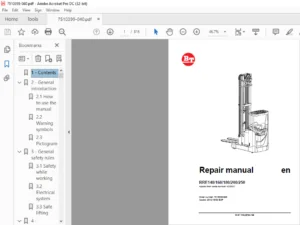
BT PRIME MOVER FORKLIFT RTX35/45 RTX30DR SERVICE MANUAL RTX3530317001-UP – PDF DOWNLOAD
$31.95
BT PRIME MOVER FORKLIFT RTX35/45 RTX30DR SERVICE MANUAL RTX3530317001-UP – PDF DOWNLOAD
Instant PDF Download
Available immediately
Save to Your Device
Download & keep forever
Antivirus Scanned
100% virus-free
Trusted Worldwide
175,000+ customers
Description
BT PRIME MOVER FORKLIFT RTX35/45 RTX30DR SERVICE MANUAL RTX3530317001-UP – PDF DOWNLOAD
FILE DETAILS:
BT PRIME MOVER FORKLIFT RTX35/45 RTX30DR SERVICE MANUAL RTX3530317001-UP – PDF DOWNLOAD
Language : English
Pages : 642
Downloadable : Yes
File Type : PDF
IMAGES PREVIEW OF THE MANUAL:
TABLE OF CONTENTS:
BT PRIME MOVER FORKLIFT RTX35/45 RTX30DR SERVICE MANUAL RTX3530317001-UP – PDF DOWNLOAD
Front Cover.........................................................................  1
Ordering Spare Parts................................................................  3
Standard Codes......................................................................  5
Table of Contents...................................................................  7
Warning Symbols..................................................................... 19
	1. Warning Levels............................................................... 19
Prohibitory Symbols................................................................. 20
	1. Ordinance Symbols............................................................ 20
Safety.............................................................................. 21
	1. General Safety............................................................... 21
Battery Safety...................................................................... 25
Static Discharge Precautions........................................................ 29
Welding Safety...................................................................... 31
Introduction, Service Manual........................................................ 33
Contents, Section M................................................................. 35
	1. Machine Information.......................................................... 35
General Product Information......................................................... 37
	1. Truck Presentation........................................................... 37
		1.1. Truck Side Views....................................................... 37
		1.2. Open Back Compartment.................................................. 38
		1.3. Intended Truck Application............................................. 38
		1.4. Prohibited Truck Application........................................... 39
		1.5. Truck Data............................................................. 39
		1.6. RTX35 Dimensions....................................................... 40
		1.7. RTX45 Dimensions....................................................... 41
		1.8. RTX30DR Dimensions..................................................... 42
		1.9. Data Plate............................................................. 43
	2. Main Components.............................................................. 44
Inch (SAE) and Metric Fasteners..................................................... 47
	1. Introduction................................................................. 47
	2. Nomenclature, Threads........................................................ 48
	3. Strength Identification...................................................... 49
	4. Truck Torque Specifications.................................................. 55
	5. Conversion of Metric and English Units....................................... 56
Technical Service Data.............................................................. 59
Contents, Section P................................................................. 63
	1. Planned Maintenance.......................................................... 63
Introduction, Maintenance........................................................... 65
	1. Jacking Truck Off The Floor.................................................. 66
		1.1. Elevate Rear of Truck.................................................. 66
		1.1. Elevate Either Side of Truck........................................... 66
	2. Lubricants................................................................... 67
		2.1. Standard Conditioning.................................................. 67
		2.2. Corrosion Conditioning................................................. 67
		2.3. Cold Storage Conditioning.............................................. 68
		2.4. Freezer Conditioning................................................... 69
Service Schedule.................................................................... 71
	1. Planned Maintenance Schedule................................................. 71
	2. Planned Maintenance Procedures............................................... 75
		2.1. Services Performed Daily or Every 8 Operating Hours.................... 75
		2.2. Services Performed Weekly or Every 30 Operating Hours.................. 77
		2.3. Services Performed Monthly or Every 120 Operating Hours................ 77
		2.4. Services Performed Every Two Months or 240 Operating Hours............. 79
		2.5. Services Performed Every Three Months or 360 Operating Hours........... 79
		2.6. Services Performed Semi-Annually or Every 720 Operating Hours.......... 80
		2.7. Services Performed Annually or Every 1440 Operating Hours.............. 81
Lubrication Chart................................................................... 83
Oil and Grease Specifications....................................................... 84
	1. Lubricants................................................................... 84
	2. Grease Location Point........................................................ 85
	3. Chain Adjustment Points...................................................... 86
Contents, Section S................................................................. 87
	1. Service Instructions......................................................... 87
Chassis............................................................................. 89
	1. Theory of Operation.......................................................... 89
	2. Maintenance.................................................................. 89
	3. Troubleshooting.............................................................. 89
	4. Repair and Rebuild........................................................... 90
		4.1. Dash................................................................... 92
		4.2. Motor Compartment Door................................................. 92
		4.3. Left Side Panel (Exterior)............................................. 93
		4.4. Left Operator Compartment Panel........................................ 95
		4.5. Main Electronic Card Panel............................................. 96
		4.6. Floor Board............................................................ 97
		4.7. Clipboard.............................................................. 98
Battery Compartment................................................................. 99
	1. Theory of Operation.......................................................... 99
	2. Maintenance.................................................................. 99
	3. Troubleshooting.............................................................. 99
	4. Repair and Rebuild...........................................................100
		4.1. Battery Stop Plates....................................................100
		4.2. Battery Rollers........................................................101
Operator Controls...................................................................103
	1. Theory of Operation..........................................................103
	2. Maintenance..................................................................103
	3. Troubleshooting..............................................................103
		3.1. Control Handle Recalibration...........................................103
	4. Repair and Rebuild...........................................................104
		4.1. Control Handle.........................................................105
		4.2. Control Handle Shell...................................................107
		4.3. Throttle Potentiometer.................................................109
		4.4. Lift/Lower Pot Return Spring...........................................111
		4.5. Lift/lower Knob Installation...........................................111
		4.6. Lift/lower Potentiometer...............................................112
		4.7. Tilt/Sideshift Switch Card.............................................113
		4.8. Reach/Retract Switches.................................................115
Brake Pedal.........................................................................117
	1. Theory of Operation..........................................................117
	2. Maintenance..................................................................117
		2.1. Adjustment.............................................................117
	3. Troubleshooting..............................................................117
	4. Repair and Rebuild...........................................................118
		4.1. Pedal Removal..........................................................120
		4.2. Bearing Replacement....................................................120
		4.3. Pedal Reassembly.......................................................121
Operator Compartment (Internal Fittings)............................................123
	1. Theory of Operation..........................................................123
	2. Maintenance..................................................................123
	3. Troubleshooting..............................................................123
	4. Repair and Rebuild...........................................................124
		4.1. Operator Fan...........................................................125
Overhead Guard......................................................................127
	1. Theory of Operation..........................................................127
	2. Maintenance..................................................................127
	3. Troubleshooting..............................................................127
	4. Repair and Rebuild...........................................................127
Decals..............................................................................129
	1. Decal with Protective Sheet..................................................129
	2. Decal without Protective Sheet...............................................129
Electric Motors.....................................................................131
	1. Theory of Operation..........................................................131
	2. Maintenance..................................................................131
	3. Troubleshooting..............................................................133
	4. Repair and Repair............................................................134
		4.1. Pump Motor.............................................................134
		4.2. Drive Motor............................................................140
		4.3. Brush Replacement......................................................144
Steering Motor......................................................................147
	1. Theory of Operation..........................................................147
	2. Maintenance..................................................................147
	3. Troubleshooting..............................................................147
	4. Repair and Rebuild...........................................................147
		4.1. Steering Motor.........................................................149
		4.2. Steering Motor Gear....................................................150
Fan Motor...........................................................................151
	1. Theory of Operation..........................................................151
	2. Maintenance..................................................................151
	3. Troubleshooting..............................................................151
	4. Repair and Rebuild...........................................................151
Transmission........................................................................153
	1. Theory of Operation..........................................................153
	2. Maintenance..................................................................153
		2.1. Fluid Changing Procedure...............................................153
		2.2. Leakage................................................................154
	3. Troubleshooting..............................................................155
	4. Repair and Rebuild...........................................................157
		4.1. Transmission...........................................................158
		4.2. Axle Sealing Ring......................................................174
Electromagnetic Brake...............................................................177
	1. Theory of Operation..........................................................177
	2. Maintenance..................................................................177
		2.1. New Brake Air Gap Adjustment...........................................177
		2.2. Coil Check On Brake....................................................178
		2.3. Friction Plate.........................................................178
	3. Troubleshooting..............................................................178
	4. Repair and Rebuild...........................................................178
		4.1. Brake Assembly.........................................................181
		4.2. Brake, Armature and Magnetic Coil......................................183
Drive Wheel.........................................................................185
	1. Theory of Operation..........................................................185
	2. Maintenance..................................................................185
	3. Troubleshooting..............................................................185
	4. Repair and Rebuild...........................................................186
Non-Braking Caster Assembly, RTX35..................................................189
	1. Theory of Operation..........................................................189
	2. Maintenance..................................................................189
		2.1. Caster Spring Adjustment...............................................189
		2.1. Caster Stop Adjustment.................................................189
	3. Troubleshooting..............................................................191
	4. Repair and Rebuild...........................................................191
		4.1. Caster Assembly........................................................192
		4.2. Thrust Bearing.........................................................193
		4.3. Caster Springs.........................................................195
Non-Braking Caster Wheels, RTX35....................................................197
	1. Theory of Operation..........................................................197
	2. Maintenance..................................................................197
		2.1. Inspection.............................................................197
	3. Troubleshooting..............................................................197
	4. Repair and Rebuild...........................................................198
Braking Caster Assembly, RTX45/ RTX30DR.............................................201
	1. Theory of Operation..........................................................201
	2. Maintenance..................................................................201
		2.1. Caster Brake Adjustment................................................201
	3. Troubleshooting..............................................................202
	4. Repair and Rebuild...........................................................203
Braking Caster Wheel Assembly, RTX45/RTX30DR........................................205
	1. Theory of Operation..........................................................205
	2. Maintenance..................................................................205
	3. Troubleshooting..............................................................205
	4. Repair and Rebuild...........................................................206
Load Wheels.........................................................................209
	1. Theory of Operation..........................................................209
	2. Maintenance..................................................................209
	3. Troubleshooting..............................................................209
	4. Repair and Rebuild...........................................................210
		4.1. Tandem Load Wheels.....................................................210
		4.2. Single Load Wheels.....................................................213
Steering Wheel......................................................................215
	1. Theory of Operation..........................................................215
	2. Maintenance..................................................................215
	3. Troubleshooting..............................................................215
	4. Repair and Rebuild...........................................................216
		4.1. Steering Wheel.........................................................217
		4.2. Steer Tach.............................................................218
Steering Bearing....................................................................219
	1. Theory of Operation..........................................................219
	2. Maintenance..................................................................219
	3. Troubleshooting..............................................................219
	4. Repair and Rebuild...........................................................220
Electrical Functions................................................................223
	1. Theory of Operation..........................................................223
		1.1. Start Up Battery Connected.............................................228
		1.2. Start Up E-Stop Released/Key ON........................................230
		1.3. Steering Components....................................................232
		1.4. Brake Release..........................................................240
		1.5. Travel Request, Forks-First............................................242
		1.6. Travel Request, Forks-Trailing.........................................246
		1.7. Plug Braking...........................................................250
		1.8. 12-Volt Power Supply...................................................254
		1.9. 7.35-Volt Power Supplies...............................................256
		1.10. Limit Switches........................................................258
		1.11. Height Indicator......................................................262
		1.12. Drive Motor Brush Wear Indicator Switches.............................265
		1.13. Pump Motor Brush Wear Indicator Switches..............................266
		1.14. Safety Check..........................................................267
		1.15. Shunt Power Cable.....................................................269
	2. Maintenance..................................................................302
		2.1. Wiring.................................................................302
		2.2. Definitions............................................................303
		2.3. Shorts to Frame Test...................................................304
	3. Troubleshooting..............................................................308
Battery.............................................................................311
	1. Theory of Operation..........................................................311
	2. Maintenance..................................................................311
		2.1. Inspection and Care....................................................311
		2.2. Battery Exterior Cleaning..............................................312
		2.3. Charging...............................................................312
		2.4. Storage................................................................313
		2.5. Battery History Record.................................................313
	3. Troubleshooting..............................................................314
	4. Repair and Rebuild...........................................................315
Battery Connector...................................................................317
	1. Theory of Operation..........................................................317
	2. Maintenance..................................................................317
		2.1. Inspection.............................................................317
	3. Troubleshooting..............................................................317
	4. Repair and Rebuild...........................................................318
Lights..............................................................................321
	1. Theory of Operation..........................................................321
	2. Maintenance..................................................................321
	3. Troubleshooting..............................................................321
	4. Repair and Rebuild...........................................................322
		4.1. Overhead Guard Lights..................................................322
Horn................................................................................323
	1. Theory of Operation..........................................................323
	2. Maintenance..................................................................323
	3. Troubleshooting..............................................................323
	4. Repair and Rebuild...........................................................324
Start/Stop Switches.................................................................325
	1. Theory of Operation..........................................................325
	2. Maintenance..................................................................325
		2.1. Key Switch (S17) Inspection............................................325
		2.2. Disconnect Switch (S21) Inspection.....................................325
	3. Troubleshooting..............................................................326
	4. Repair and Rebuild...........................................................326
		4.1. Key Switch (S17).......................................................326
		4.2. Disconnect (Stop) Switch (S21).........................................327
Proximity Switches..................................................................329
	1. Theory of Operation..........................................................329
		1.1. Mast Switch (S31)......................................................329
		1.2. Staging Switch (S45)...................................................329
	2. Maintenance..................................................................330
		2.1. Mast Switch (S31) Adjustment...........................................330
		2.1. Staging Switch (S45) Adjustment........................................330
	3. Troubleshooting..............................................................331
	4. Repair and Rebuild...........................................................331
		4.1. Mast Switch (S31)......................................................331
		4.2. Staging Switch (S45)...................................................332
Control Cable and Harness...........................................................333
	1. Theory of Operation..........................................................333
		1.1. Fuses..................................................................333
		1.2. Auxiliary Power Hook-up for On-board Terminal (Optional)...............334
	2. Maintenance..................................................................334
		2.1. Wiring Harness.........................................................334
		2.2. Power Cables...........................................................335
	3. Troubleshooting..............................................................335
	4. Repair and Rebuild...........................................................335
Contactors..........................................................................337
	1. Theory of Operation..........................................................337
	2. Maintenance..................................................................337
		2.1. Contactor Tip Inspection...............................................337
		2.2. Testing Resistance.....................................................338
	3. Troubleshooting..............................................................338
	4. Repair and Rebuild...........................................................338
		4.1. Main Contactor.........................................................339
		4.2. Directional Contactors.................................................341
		4.3. Lift Bypass Contactor..................................................343
Transistor Panel....................................................................345
	1. Theory of Operation..........................................................345
		1.1. Drive Motor Connections................................................345
		1.2. Pump Motor Connections.................................................347
	2. Maintenance..................................................................349
		2.1. Circuit Check..........................................................349
Micro Auxiliary Switches............................................................351
	1. Theory of Operation..........................................................351
	2. Maintenance..................................................................352
	3. Troubleshooting..............................................................352
	4. Repair and Rebuild...........................................................352
		4.1. Lift Limit Override Switch (S33).......................................352
		4.2. Light and Fan Switches (S96, S97 and S99) [Optional]...................353
Main Electronic Card................................................................355
	1. Theory of Operation..........................................................355
		1.1. Connectivity to Truck..................................................355
		1.2. Display................................................................356
		1.3. Time Setting SA........................................................358
	2. Maintenance..................................................................364
		2.1. RV2 Adjustment Procedure...............................................364
		2.2. Adjustment Procedures for Setting Brake Switch and Brake Transducer....365
	3. Troubleshooting..............................................................366
		3.1. Warning/Caution Codes..................................................366
		3.2. Error codes............................................................369
		3.3. Running time...........................................................378
		3.4. Programming Parameters.................................................378
	4. Repair and Rebuild...........................................................392
Sensors and Switches................................................................393
	1. Theory of Operation..........................................................393
		1.1. Wheel Direction Sensor (S65)...........................................393
		1.2. Platform (Right Foot) Switch (S108)....................................393
		1.3. Steer Stop Proximity Sensor A (S66) and Sensor B (S67).................394
		1.4. Drive Motor Speed (S64)/Direction Sensors (S125).......................394
	2. Maintenance..................................................................394
		2.1. Wheel Direction Sensor (S65) Adjustment................................394
		2.2. Steer Stop Proximity Sensor A (S66) and Sensor B (S67) Adjustment......395
	3. Troubleshooting..............................................................396
	4. Repair and Rebuild...........................................................396
		4.1. Wheel Direction Sensor (S65)...........................................396
		4.2. Platform (Right Foot) Switch (S108)....................................397
		4.3. Steer Stop Proximity Sensor A (S66) and B (S67)........................398
		4.4. Drive Motor Speed (S64) and Direction (S125) Sensors...................399
Hydraulic System....................................................................401
	1. Theory of Operation..........................................................401
		1.1. Control Handle Interface, Hydraulic Control Operation..................402
		1.2. Supply.................................................................406
		1.3. Lifting................................................................408
		1.4. Lowering...............................................................410
		1.5. Low Speed Extend (RTX35/30DR)..........................................412
		1.6. Low Speed Extend (RTX45)...............................................414
		1.7. High Speed Extend (RTX35/30DR).........................................416
		1.8. High Speed Extend (RTX45)..............................................418
		1.9. Low Speed Retract (RTX35/30DR).........................................420
		1.10. Low Speed Retract (RTX45).............................................422
		1.11. High Speed Retract (RTX35/30DR).......................................424
		1.12. High Speed Retract (RTX45)............................................426
		1.13. Reach Impact..........................................................428
		1.14. Fork Tilt Up..........................................................432
		1.15. Fork Tilt Down........................................................436
		1.16. Left Sideshift........................................................440
		1.17. Right Sideshift.......................................................442
	2. Maintenance..................................................................449
		2.1. Changing Hydraulic System Fluid........................................449
		2.2. System Draining........................................................450
		2.3. System Refilling.......................................................451
		2.4. Bleeding Hydraulic System..............................................451
		2.5. Setting Lift/Auxiliary Pressure Relief with a Rated Load...............452
		2.6. Hydraulic Lowering Rate Adjustment.....................................453
		2.7. Hydraulic Pump Testing.................................................453
	3. Troubleshooting..............................................................454
	4. Repair and Rebuild...........................................................455
		4.1. Control Valve..........................................................458
		4.2. Hydraulic Reservoir Tank...............................................462
		4.3. Hydraulic Filter.......................................................465
		4.4. Hydraulic Adapter......................................................466
		4.5. Hydraulic (Lift) Pump..................................................468
Staging Cylinder....................................................................475
	1. Theory of Operation..........................................................475
	2. Maintenance..................................................................475
		2.1. Inspection.............................................................475
	3. Troubleshooting..............................................................475
	4. Repair and Rebuild...........................................................476
Freelift Cylinder...................................................................485
	1. Theory of Operation..........................................................485
	2. Maintenance..................................................................485
		2.1. Inspection.............................................................485
	3. Troubleshooting..............................................................485
	4. Repair and Rebuild...........................................................486
Reach Cylinder......................................................................493
	1. Theory of Operation..........................................................493
	2. Maintenance..................................................................493
		2.1. Inspection.............................................................493
	3. Troubleshooting..............................................................494
	4. Repair and Rebuild...........................................................494
RTX35 Reach Cylinder................................................................495
RTX45 Reach Cylinder................................................................499
RTX30DR Reach Cylinder..............................................................504
Tilt Cylinder.......................................................................509
	1. Theory of Operation..........................................................509
	2. Maintenance..................................................................509
		2.1. Inspection.............................................................509
	3. Troubleshooting..............................................................510
	4. Repair and Rebuild...........................................................510
RTX35 Tilt Cylinder.................................................................511
RTX45 Tilt Cylinder.................................................................515
RTX30DR Tilt Cylinder...............................................................519
Mast, 3 Stage.......................................................................523
	1. Theory of Operation..........................................................523
	2. Maintenance..................................................................523
		2.1. Visual Inspection......................................................523
		2.2. Chain Inspection.......................................................523
		2.3. Lift Chain Lubrication.................................................528
		2.4. Mast Lift Chain Adjustment.............................................529
	3. Troubleshooting..............................................................530
	4. Repair and Rebuild...........................................................530
Crosshead...........................................................................543
	1. Theory of Operation..........................................................543
	2. Maintenance..................................................................543
	3. Troubleshooting..............................................................543
	4. Repair and Rebuild...........................................................543
Sideshifter (S/N 30317001-34131000).................................................549
	1. Theory of Operation..........................................................549
	2. Maintenance..................................................................549
		2.1. Periodic Maintenance...................................................549
		2.2. Sideshift Carriage Mounting............................................550
	3. Troubleshooting..............................................................551
		3.1. No Sideshifting........................................................551
		3.2. Very Slow Sideshifting.................................................551
		3.3. Irregular Sideshifting.................................................552
	4. Repair and Rebuild...........................................................553
		4.1. Sideshift Carriage.....................................................554
		4.2. Upper Pad..............................................................555
		4.3. Lower Pad..............................................................555
		4.4. Cylinder...............................................................557
Sideshifter (S/N 34131001 - UP).....................................................559
	1. Theory of Operation..........................................................559
	2. Maintenance..................................................................559
	3. Troubleshooting..............................................................560
		3.1. No Sideshifting........................................................560
		3.2. Very Slow Sideshifting.................................................560
		3.3. Irregular Sideshifting.................................................561
	4. Repair and Rebuild...........................................................562
		4.1. Sideshift Carriage.....................................................563
		4.2. Upper Pad..............................................................564
		4.3. Lower Pad..............................................................564
		4.4. Cylinder...............................................................565
RTX 35 Single Reach.................................................................567
	1. Theory of Operation..........................................................567
	2. Maintenance..................................................................567
		2.1. Carriage/reach Retract Bumpers.........................................568
		2.2. Carriage Roller Bearings...............................................568
		2.3. Reach Adjustment.......................................................568
	3. Troubleshooting..............................................................570
	4. Repair and Rebuild...........................................................571
		4.1. Reach..................................................................575
		4.2. Front Frame............................................................575
		4.3. Outer Arm..............................................................576
		4.4. Inner Arm..............................................................577
		4.5. Rear Frame.............................................................578
		4.6. Reach Cylinder.........................................................579
		4.7. Carriage Bearings......................................................580
RTX45 Single Reach..................................................................581
	1. Theory of Operation..........................................................581
	2. Maintenance..................................................................581
		2.1. Carriage/reach Retract Bumpers.........................................581
		2.2. Carriage Roller Bearings...............................................581
	3. Troubleshooting..............................................................581
	4. Repair and Rebuild...........................................................582
		4.1. Reach..................................................................584
		4.2. Front Frame............................................................584
		4.3. Outer Arm..............................................................585
		4.4. Inner Arm..............................................................586
		4.5. Rear Frame.............................................................587
		4.6. Reach Cylinder.........................................................588
		4.7. Reach Front Frame Wear Plate...........................................589
		4.8. Carriage Bearings......................................................590
RTX30 Double Reach Mechanism........................................................591
	1. Theory of Operation..........................................................591
	2. Maintenance..................................................................591
	3. Troubleshooting..............................................................591
	4. Repair.......................................................................591
	5. Rebuild......................................................................592
		5.1. Fork Frame.............................................................594
		5.2. Forward Frame..........................................................596
		5.3. Extend Reach...........................................................598
		5.4. Arm Assembly...........................................................598
		5.5. Rear Frame.............................................................607
Forks...............................................................................611
	1. Theory of Operation..........................................................611
	2. Maintenance..................................................................611
		2.1. Inspection.............................................................611
	3. Troubleshooting..............................................................612
	4. Repair and Rebuild...........................................................612
Lights and Alarms (Optional)........................................................615
	1. Theory of Operation..........................................................615
	2. Maintenance..................................................................615
	3. Troubleshooting..............................................................615
	4. Repair and Rebuild...........................................................616
		4.1. Warning Lights.........................................................616
		4.2. Working Lights.........................................................617
		4.3. Travel/Back-up Alarm...................................................618
Height Indicator....................................................................619
	1. Theory of Operation..........................................................619
	2. Maintenance..................................................................619
	3. Troubleshooting..............................................................619
		3.1. Error Code 13..........................................................619
	4. Repair and Rebuild...........................................................620
		4.1. Pulse Sensor...........................................................623
		4.2. Cable..................................................................624
		4.3. Pulley.................................................................624
Load Backrest.......................................................................625
	1. Theory of Operation..........................................................625
	2. Maintenance..................................................................625
	3. Troubleshooting..............................................................625
	4. Repair and Rebuild...........................................................626
Electrical Heater (Upper Chassis and Handle Assembly)...............................629
	1. Theory of Operation..........................................................629
	2. Maintenance..................................................................629
	3. Troubleshooting..............................................................629
	4. Repair and Rebuild...........................................................630
Electrical Heater (Lower Chassis and Pedal Assembly)................................633
	1. Theory of Operation..........................................................633
	2. Maintenance..................................................................633
	3. Troubleshooting..............................................................633
	4. Repair and Rebuild...........................................................634
	A...............................................................................637
	B...............................................................................637
	C...............................................................................637
	D...............................................................................637
	E...............................................................................638
	F...............................................................................638
	G...............................................................................638
	H...............................................................................638
	K...............................................................................638
	L...............................................................................638
	M...............................................................................639
	O...............................................................................639
	P...............................................................................639
	R...............................................................................639
	S...............................................................................639
	T...............................................................................640
	W...............................................................................640
Index...............................................................................637
Back Cover..........................................................................642
DESCRIPTION:
BT PRIME MOVER FORKLIFT RTX35/45 RTX30DR SERVICE MANUAL RTX3530317001-UP – PDF DOWNLOAD
General Product Information
The RTX35, RTX45, and RTX30DR are battery-powered reach trucks intended solely to be operated indoors carrying pallets or similar load carriers. The trucks are equipped with a steering wheel and control handle with all controls for operating within easy access. The trucks have various maximum lifting capacities (review the data plate on the truck to note the maximum lifting capacity).
The RTX35 truck is equipped with a 24 or 36-volt electrical system. RTX45 and RTX30DR trucks are only available with a 36-volt electrical system. Truck speed is regulated by means of a transistor regulator to provide control of acceleration and speed while driving. Forks and auxiliary functions are controlled by means of a transistor regulator. The control of the lift and auxiliary functions and speed and positioning of the forks when stacking are done electrically with switches on the control handle.
The trucks can be fitted with different accessories including sideshift, warning light, lights/fan package, travel alarm, and adjustable driving lights. Trucks can be specially equipped to work in cold conditions.
S.S 05/01/2025