Trusted Business
Verified & Licensed
Virus Free Files
100% Safe Downloads
Secure Payment
SSL Protected
Instant Delivery
Available Immediately
BT Forklift SWE120L, SWE160D Service Manual 922602 – PDF DOWNLOAD
$26.95
BT Forklift SWE120L SWE160D Service Manual 922602 – PDF DOWNLOAD
Instant PDF Download
Available immediately
Save to Your Device
Download & keep forever
Antivirus Scanned
100% virus-free
Trusted Worldwide
175,000+ customers
Description
BT Forklift SWE120L, SWE160D Service Manual 922602 – PDF DOWNLOAD
FILE DETAILS:
BT Forklift SWE120L, SWE160D Service Manual 922602 – PDF DOWNLOAD
Language : English
Pages : 168
Downloadable : Yes
File Type : PDF
IMAGES PREVIEW OF THE MANUAL:
TABLE OF CONTENTS:
BT Forklift SWE120L, SWE160D Service Manual 922602 – PDF DOWNLOAD
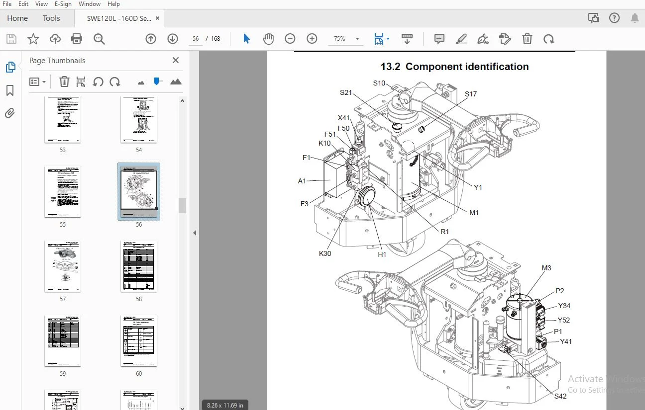
1- Table of contents................................................................................  3
2- Technical data - M4..............................................................................  9
3- Introduction Maintenance - P1.................................................................... 13
	3.1 Safety regulations with maintenance work.................................................... 13
	3.2 Cleaning and washing........................................................................ 15
		3.2.1 External cleaning..................................................................... 15
		3.2.2 Cleaning the motor compartment........................................................ 15
		3.2.3 Electrical components................................................................. 15
	3.3 Safe lifting................................................................................ 16
4- Preventive maintenance - P2...................................................................... 17
	4.1 Maintenance schedule........................................................................ 17
	4.2 Lubrication schedule........................................................................ 22
5- Oil and grease specification - P3................................................................ 25
6- Tools - P4....................................................................................... 27
	6.1 Super Seal connectors....................................................................... 27
	6.2 AMP connectors.............................................................................. 28
		6.2.1 AMP Connectors, 040 series............................................................ 29
	6.3 Molex connectors............................................................................ 29
	6.4 Grease guns................................................................................. 30
	6.5 Other tools................................................................................. 31
7- Support arms - 0350.............................................................................. 33
	7.1 Greasable support arms...................................................................... 33
8- Engine suspension- 0450.......................................................................... 35
	8.1 Component parts............................................................................. 35
		8.1.1 Component List........................................................................ 36
		8.1.2 Adjusting play, turning tube mounting................................................. 37
9- Electric drive motor - 1760...................................................................... 39
	9.1 Component parts............................................................................. 39
		9.1.1 Dismantling of motor from truck....................................................... 40
		9.1.2 Assembling............................................................................ 40
	9.2 Service/Repairs............................................................................. 41
		9.2.1 Dismantling of motor.................................................................. 41
		9.2.2 Assembling of motor................................................................... 42
		9.2.3 Cleaning.............................................................................. 42
10- Drive unit/gear - 2550.......................................................................... 43
	10.1 Component parts............................................................................ 44
	10.2 Leakage from top cover..................................................................... 45
	10.3 Changing of the drive shaft’s sealing ring................................................. 46
		10.3.1 Dismantling.......................................................................... 46
		10.3.2 Assembling........................................................................... 46
11- Electro magnetic brake - 3370................................................................... 47
	11.1 Main components............................................................................ 47
		11.1.1 Serial number 570989-................................................................ 47
	11.2 Maintenance................................................................................ 48
		11.2.1 Exchange of brake disc............................................................... 48
12- Steering - 4000................................................................................. 49
	12.1 Component parts, tiller arm................................................................ 49
	12.2 Adjustments................................................................................ 50
		12.2.1 Adjusting of brake microswitch....................................................... 50
	12.3 Tiller arm handle.......................................................................... 51
		12.3.1 Dismantling/Assembling............................................................... 53
			Changing of signal button/switch (9, 10)................................................ 53
			Changing of lift/lowering button (13)................................................... 54
			Changing of pushbutton (16)............................................................. 54
13- Electrical systems - 5000....................................................................... 55
	13.1 General.................................................................................... 55
		13.1.1 Part numbers......................................................................... 55
	13.2 Component identification................................................................... 56
		13.2.1 Component list....................................................................... 58
	13.3 Electrical wiring diagram.................................................................. 60
		13.3.1 Symbol list.......................................................................... 60
		13.3.2 Overview............................................................................. 61
		13.3.3 Electrical wiring diagrams........................................................... 62
	13.4 Functional description..................................................................... 68
		13.4.1 Starting the truck................................................................... 68
		13.4.2 Driving.............................................................................. 68
		13.4.3 Neutral speed reduction.............................................................. 68
		13.4.4 Neutral speed reduction on slopes.................................................... 68
		13.4.5 Braking.............................................................................. 68
		13.4.6 Lifting the forks.................................................................... 69
		13.4.7 Lifting the support arms............................................................. 69
		13.4.8 Lowering the forks................................................................... 69
		13.4.9 Lowering the support arms............................................................ 69
		13.4.10 Horn................................................................................ 69
		13.4.11 Hour meter.......................................................................... 69
		13.4.12 Transistor regulator................................................................ 70
		13.4.13 Spider expansion unit (SEU) (option)................................................ 70
		13.4.14 TLS - Truck log system (optional)................................................... 73
			General................................................................................. 73
			Registration............................................................................ 73
			Logging in/out SD16..................................................................... 73
			Logging in/out S16...................................................................... 73
			Collision sensor........................................................................ 74
			Settings................................................................................ 74
		13.4.15 ID unit (optional).................................................................. 75
			General................................................................................. 75
			Installation............................................................................ 75
			Settings................................................................................ 76
	13.5 Parameters................................................................................. 78
		13.5.1 General.............................................................................. 78
		13.5.2 Viewing parameters - without the CAN service key..................................... 78
		13.5.3 Adjusting operator parameters - without the CAN service key.......................... 79
		13.5.4 Viewing & changing parameters - CAN service key connected............................ 80
			Changing a parameter.................................................................... 81
		13.5.5 Operator parameters.................................................................. 82
		13.5.6 Parameter description................................................................ 82
			Parameter 1............................................................................. 82
			Parameter 2............................................................................. 82
			Parameter 3............................................................................. 82
			Parameter 4............................................................................. 82
			Parameter 5............................................................................. 83
		13.5.7 Service parameters................................................................... 84
		13.5.8 Parameter description................................................................ 85
			Parameter 10............................................................................ 85
			Parameter 14............................................................................ 85
			Parameter 15 - Non-configurable options................................................. 85
			Setting Non-configurable options........................................................ 85
			Parameter 16 - Configurable option #1................................................... 86
			Parameter 17 - Configurable option #2................................................... 86
			Parameter 18 - Configurable option #3................................................... 86
			Parameter 19 - Configurable option #4................................................... 86
			Parameter 20............................................................................ 87
			Parameter 21............................................................................ 87
			Recommendation on parameter setting for freely ventilated batteries..................... 88
			Instructions for verifying parameter setting............................................ 89
			Recommendation on parameter setting for valve- controlled batteries (VRLA).............. 90
			Instructions for verifying parameter setting............................................ 91
			Parameter 22............................................................................ 91
			Parameter 25............................................................................ 91
			Parameter 28............................................................................ 91
			Parameter 39............................................................................ 92
			Login method and driver parameter access................................................ 92
			Expanded keypad - General............................................................... 92
			Expanded keypad - Programming........................................................... 92
		13.5.9 Configurable “Option” Parameters..................................................... 95
			General................................................................................. 95
			Summary of base options................................................................. 95
			Convention for configurable options..................................................... 96
			Detailed option parameter tables........................................................ 98
	13.6 Diagnostic and troubleshooting.............................................................108
		13.6.1 General..............................................................................108
		13.6.2 Error code history...................................................................109
		13.6.3 Error codes..........................................................................109
		13.6.4 Transistor regulator errors..........................................................122
			Resetting errors........................................................................123
			Safety..................................................................................123
		13.6.5 Built-in Test Function...............................................................124
			Digital inputs/outputs test mode........................................................125
			Inputs check............................................................................125
			Outputs check...........................................................................126
			Option buttons check....................................................................127
			Display test mode.......................................................................127
	13.7 Technical specifications - Curtis 1243.....................................................128
14- Hydraulic system - 6000.........................................................................129
	14.1 General....................................................................................129
	14.2 Hydraulic diagram and components...........................................................129
		14.2.1 Main components......................................................................130
		14.2.2 Description..........................................................................130
			Lift....................................................................................130
			Lowering................................................................................130
			Operating pressure......................................................................130
			Relief valve............................................................................131
			Pressure switch.........................................................................131
15- Lifting mast - 7000.............................................................................133
	15.1 Adjusting the measurement between the guide and the mast...................................133
	15.2 Grease the beam flanges and beam ribs......................................................134
	15.3 Main lift chain system -...................................................................135
		15.3.1 General..............................................................................135
		15.3.2 Checking the chain setting...........................................................135
		15.3.3 Chain inspection.....................................................................135
		15.3.4 Noise................................................................................135
		15.3.5 Surface rust.........................................................................135
		15.3.6 Rusty links..........................................................................135
		15.3.7 Stiff links..........................................................................136
		15.3.8 Bolt rotation........................................................................136
		15.3.9 Loose bolts..........................................................................136
		15.3.10 Outline wear........................................................................137
		15.3.11 Stretching..........................................................................138
		15.3.12 Damage..............................................................................138
		15.3.13 Damaged discs.......................................................................139
		15.3.14 Damaged bolts.......................................................................139
		15.3.15 Dirty chain.........................................................................139
		15.3.16 Cleaning............................................................................139
		15.3.17 Lubrication.........................................................................139
16- Battery charger (built-in) - 8340...............................................................141
	16.1 General....................................................................................141
	16.2 Technical data - charger...................................................................142
	16.3 Charging...................................................................................142
		Machine numbers 723984-936512...............................................................142
		Machine numbers 936513-.....................................................................143
	16.4 Troubleshooting and service................................................................143
	16.5 Setting the charger (applies to machine numbers 723984-936512).............................144
		Freely ventilated batteries.................................................................144
		Valve-regulated batteries...................................................................144
		16.5.1 Current levels at different charger settings (applies to machine numbers 936513-)....145
			Freely ventilated batteries.............................................................145
			Valve-regulated batteries (Evolution type)..............................................146
17- TruckCom........................................................................................147
	17.1 General....................................................................................147
	17.2 Connection.................................................................................147
	17.3 Layout.....................................................................................148
		17.3.1 Main program screen..................................................................148
		17.3.2 Nodes................................................................................148
		17.3.3 Icons................................................................................149
		17.3.4 Tool buttons and menu bar............................................................149
		17.3.5 Information window...................................................................150
		17.3.6 Status bar...........................................................................150
	17.4 Connection function........................................................................150
	17.5 Disconnection function.....................................................................150
	17.6 Downloading program function...............................................................151
		17.6.1 Normal downloading (truck with key)..................................................151
		17.6.2 Normal downloading (truck with keypad)...............................................151
		17.6.3 Emergency downloading (truck with keypad)............................................152
		17.6.4 Emergency downloading (truck with keypad)............................................152
		17.6.5 Downloading in old versions of logic card............................................152
	17.7 Truck report function......................................................................153
	17.8 Parameters function........................................................................154
	17.9 Diagnostics function.......................................................................154
		17.9.1 Representation of signal colours.....................................................155
		17.9.2 “Tiller arm” tab.....................................................................155
		17.9.3 “Drive Controller” tab (transistor regulator driving)................................156
		17.9.4 “Pump controller” tab (transistor regulator pump)....................................157
		17.9.5 “EPS” (steering servo tab)...........................................................158
		17.9.6 SEU tab (Extra I/O module)...........................................................159
	17.10 Other menu functions......................................................................159
		17.10.1 Save to file........................................................................159
		17.10.2 Download from file..................................................................159
		17.10.3 Reset CAN adapter...................................................................160
		17.10.4 Delete error code log...............................................................160
		17.10.5 Reset hour meter....................................................................160
		17.10.6 Read error code log.................................................................160
		17.10.7 Adjust date and time................................................................160
		17.10.8 Adjusting the hour meter on older cards.............................................160
		17.10.9 Help................................................................................160
			About the TruckCom application..........................................................160
		17.10.10 Exit...............................................................................160
	17.11 Specifications............................................................................161
	17.12 Installation..............................................................................161
		17.12.1 Installation on a PC with Windows® 95/98............................................161
		17.12.2 Installation on a PC with Windows XP/ 2000..........................................162
			Changes in Windows® Control Panel.......................................................164
		17.12.3 Installation on a PC with Windows NT................................................167
		17.12.4 In case of communication problems with CAN..........................................167
		17.12.5 To uninstall........................................................................167
DESCRIPTION:
BT Forklift SWE120L, SWE160D Service Manual 922602 – PDF DOWNLOAD
- All points in the service program should be carried out to attain the highest safety and the least possible downtime. The service intervals are only a guide and do not need to be followed to the letter. The operator may adapt them to local conditions, but it is important that the intervals comply with BT’s minimum requirements.
- The service intervals are based on the running times and can be adapted to most normal 8 hour shifts. The service interval may be shortened if the truck is used more frequently or in more demanding situations, e.g cold store, dusty or corrosive situations.
- Ensure the truck is given a regular maintenance service after every 500 driving hours. The truck’s safety, efficiency and service life is dependent on the service and maintenance it is given.
- Only use BT approved spare parts when service and repair work are carried out.
S.S 06/01/2025