Aircraft Navy Model F/A-18E/F 165533 & Up Natops Flight Model – PDF
$43.95
Aircraft Navy Model F/A-18E/F 165533 & Up Natops Flight Model – PDF DOWNLOAD
Description
Aircraft Navy Model F/A-18E/F 165533 & Up Natops Flight Model – PDF DOWNLOAD
FILE DETAILS:
Aircraft Navy Model F/A-18E/F 165533 & Up Natops Flight Model – PDF DOWNLOAD
Language : English
Pages : 806
Downloadable : Yes
File Type : PDF
IMAGES PREVIEW OF THE MANUAL:
TABLE OF CONTENTS:
Aircraft Navy Model F/A-18E/F 165533 & Up Natops Flight Model – PDF DOWNLOAD
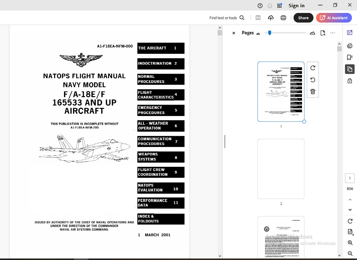
COVER 1
LETTER OF PROMULGATION 3
CONTENTS 5
LIST OF ILLUSTRATIIONS 24
RECORD OF CHANGES 31
INTERIM CHANGES SUMMARY 33
SUMMARY OF APPLICABLE TECHNICAL DIRECTIVES 35
GLOSSARY 37
PREFACE 47
PART l – THE AIRCRAFT 53
CHAPTER 1 – The Aircraft 55
Figure 1-1 General Arrangements 55
Figure 1-2 Approximate Dimensions 56
Figure 1-3 Radar Cross Section (RCS) Reduction 57
Figure 1-4 Block Numbers 59
CHAPTER 2 – Systems 61
Figure 2-1 Throttle Grips (Front Cockpit) 67
Figure 2-2 Engine Fuel Display (EFD) – Engine Parameters 68
Figure 2-3 Engine Display 70
Figure 2-4 Tank 1 and 4 Fuel CG Control and FUEL XFER Caution Schedule 75
Figure 2-5 Fuel Quantity 80
Figure 2-6 Engine Fuel Display (EFD) – Fuel Parameters 81
Figure 2-7 FUEL Display 82
Figure 2-8 Secondary Power Supply 84
Figure 2-9 Simplified Electrical Schematic 87
Figure 2-10 FCC Electrical Redundancy 90
Figure 2-11 Ground Power Panel and Placard 92
Figure 2-12 Circuit Breaker Panels 93
Figure 2-13 Exterior Lights 94
Figure 2-14 ID Strobe Patterns 95
Figure 2-15 Hydraulic Flow100
Figure 2-16 Wheel Brake and Anti-skid System108
Figure 2-17 Emergency/Parking Brake Handle111
Figure 2-18 Flight Control System Functional Diagram118
Figure 2-19 FCS Surface Deflections119
Figure 2-20 Flap Schedules124
Figure 2-21 Stick and Pedal Travel Limits129
Figure 2-22 Stick Grip FCS Controls131
Figure 2-23 SPIN Recovery Display133
Figure 2-24 GAIN ORIDE Flap Positions and Gain Schedules135
Figure 2-25 FCS Related Cautions and Cockpit Indications137
Figure 2-26 FCS Status Display138
Figure 2-27 AFCS Controls and Indicators141
Figure 2-28 Stick Grip Switches/Controls144
Figure 2-29 Throttle Grip Switches/Controls (Front Cockpit)146
Figure 2-30 Hand Controllers149
Figure 2-31 OBOGS Monitor160
Figure 2-32 Canopy Controls167
Figure 2-33 Boarding Ladder170
Figure 2-34 SJU-17 Ejection Modes171
Figure 2-35 Leg Restraint System173
Figure 2-36 Survival Kit175
Figure 2-37 GPWS HUD Roll Warning Cues183
Figure 2-38 GPWS Aural Cues183
Figure 2-39 Angle of Attack Indexer186
Figure 2-40 MUMI Display188
Figure 2-41 Menu Display192
Figure 2-42 Electronic Attitude Display Indicator193
Figure 2-43 MPCD Controls and HSI Symbology195
Figure 2-44 HUD Controls197
Figure 2-45 HUD Symbology200
Figure 2-46 HUD Symbology Degrades204
Figure 2-47 Up Front Control Display (UFCD)208
Figure 2-48 AMU Maintenance Format215
Figure 2-49 Map Loading Format216
Figure 2-50 Flight Aids Reversion Mechanization221
Figure 2-51 Equipment Status Messages222
Figure 2-52 Caution/Advisory Displays224
Figure 2-53 BIT Control Display225
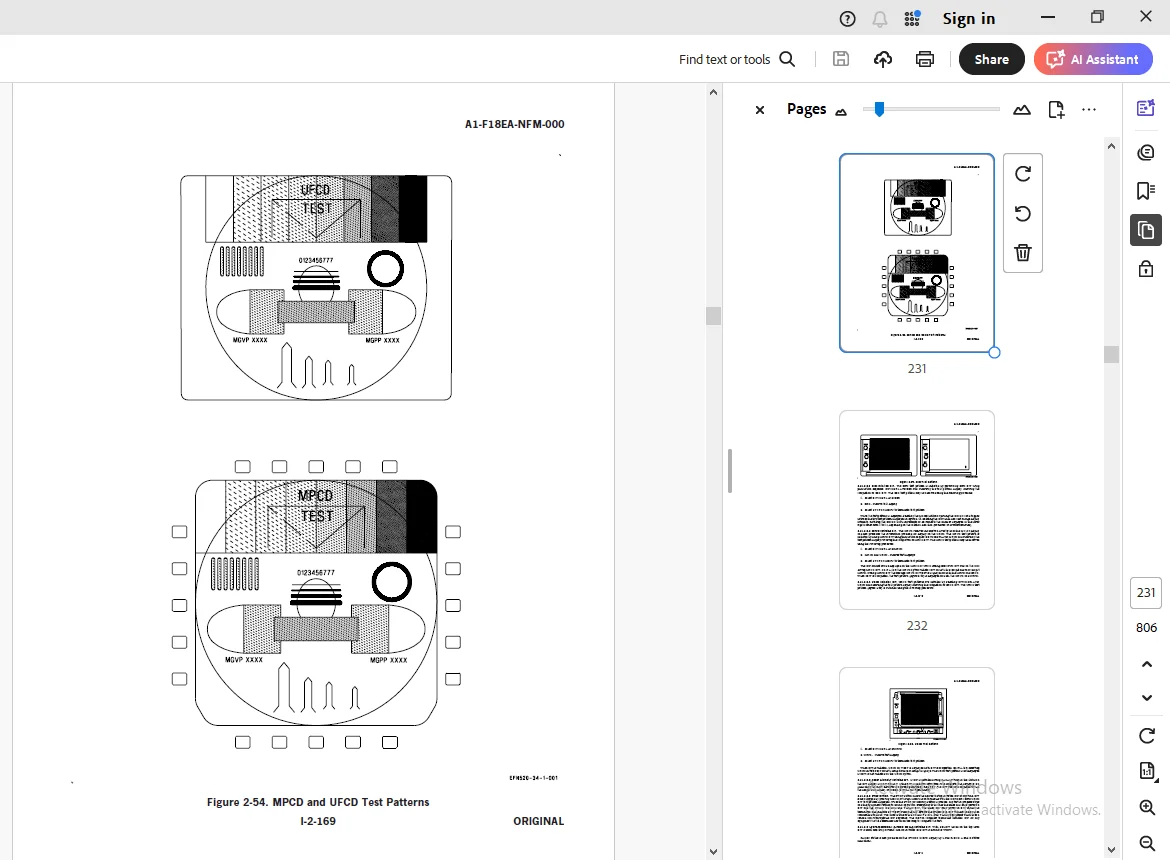
Figure 2-54 MPCD and UFCD Test Patterns231
Figure 2-55 EFD Test Pattern232
Figure 2-56 UFCD Test Pattern233
Figure 2-57 CONFIG Display (Sample)235
Figure 2-58 INS Postflight Data Display236
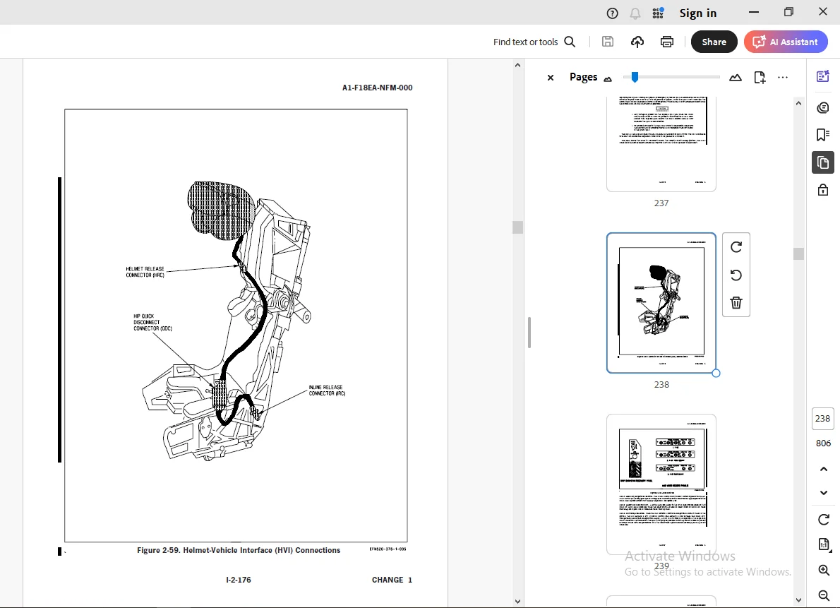
Figure 2-59 Helmet-Vehicle Interface (HVI) Connections238
Figure 2-60 HMD Controls239
Figure 2-61 Displays BIT Sublevel240
Figure 2-62 HMD Test Patterns241
Figure 2-63 HMD Error Log Display243
Figure 2-64 Coarse Alignment244
Figure 2-65 Fine Alignment246
Figure 2-66 Alignment Verification247
CHAPTER 3 – Service and Handling249
CHAPTER 4 – Operating Limitations251
Figure 4-1 Engine Operation Limitations251
Figure 4-2 Basic Aircraft Airspeed Limitations252
Figure 4-3 Subsystem Airspeed Limitations252
Figure 4-4 Gross Weight and Lateral Weight Asymmetry Limitations253
Figure 4-5 Asymmetric Stores Limitations253
Figure 4-6 AOA Limitations – Flaps AUTO255
Figure 4-7 Acceleration Limitations – Basic Aircraft (with or without empty pylons)256
Figure 4-8 Limitations with Flaps HALF or FULL258
Figure 4-9 480-Gal External Fuel Tank and ARS Carriage Limitations261
Figure 4-10 ARS Operating Limitations262
Figure 4-11 PIDS/CAS Airspeed Limitations (prior to FCC software 18E-003)262
PART ll – INDOCTRINATION265
CHAPTER 5 – Indoctrination267
Figure 5-1 Requirements for Various Flight Phases During Initial Training268
Figure 5-2 Pilot Ceiling and Visibility Restrictions Prior to Instrument Qualification270
PART lll – NORMAL PROCEDURES271
CHAPTER 6 – Flight Preparation273
CHAPTER 7 – Shore-Based Procedures277
Figure 7-1 Exterior Inspection278
Figure 7-2 Checklist Display303
Figure 7-3 Typical Field Landing Pattern310
CHAPTER 8 – Carrier-Based Procedures323
Figure 8-1 Launch Trim325
Figure 8-2 Carrier Landing Pattern333
Figure 8-3 Carrier Controlled Approach335
Figure 8-4 ACL Mode 1 and 1A Approaches338
Figure 8-5 ACL Mode 2 Approach341
CHAPTER 9 – Special Procedures343
Figure 9-1 Formation Takeoff Runway Alignments344
Figure 9-2 Formations345
Figure 9-3 ARS Control Panel351
CHAPTER 10 – Functional Checkflight Procedures363
Figure 10-1 Functional Checkflight Requirements365
PART lV – FLIGHT CHARACTERISTICS395
CHAPTER 11 – Flight Characteristics397
Figure 11-1 AHRS Channel Failure Indication and Effects411
PART V – EMERGENCY PROCEDURES413
EMERGENCY INDEX415
CHAPTER 12 – General Emergencies419
Figure 12-1 Warning/Caution/Advisory Displays421
CHAPTER 13 – Ground Emergencies477
CHAPTER 14 – Takeoff Emergencies481
Figure 14-1 Maximum Weight for 100 fpm Single Engine Rate of Climb485
CHAPTER 15 – Inflight Emergencies487
Figure 15-1 Spooldown Restart Envelope488
Figure 15-2 Windmill Restart Envelope488
Figure 15-3 Crossbleed Restart Envelope489
Figure 15-4 APU Restart Envelope489
Figure 15-5 Hydraulic Flow Diagram (Aircraft on Deck)492
Figure 15-6 Hydraulic Subsystems Malfunction Guide493
Figure 15-7 Emergency Power Distribution495
Figure 15-8 External Stores Jettison Chart507
Figure 15-9 FCS Failure Indications and Effects508
Figure 15-10 FCS Failure Indications and Effects509
Figure 15-11 FCS Failure Indications and Effects509
Figure 15-12 FCS Failure Indications and Effects510
Figure 15-13 FCS Failure Indications and Effects510
Figure 15-14 FCS Failure Indications and Effects511
Figure 15-15 FCS Failure Indications and Effects511
Figure 15-16 FCS Failure Indications and Effects512
Figure 15-17 FCS Failure Indications and Effects513
Figure 15-18 FCS Failure Indications and Effects514
Figure 15-19 FCS Failure Indications and Effects514
Figure 15-20 FCS Failure Indications and Effects515
Figure 15-21 FCS Failure Indications and Effects515
Figure 15-22 FCS Failure Indications and Effects516
Figure 15-23 FCS Failure Indications and Effects516
Figure 15-24 FCS Failure Indications and Effects517
Figure 15-25 FCS Failure Indications and Effects517
Figure 15-26 FCS Failure Indications and Effects518
Figure 15-27 FCS Failure Indications and Effects518
Figure 15-28 FCS Failure Indications and Effects519
Figure 15-29 FCS Failure Indications and Effects519
Figure 15-30 FCS Failure Indications and Effects520
Figure 15-31 FCS Failure Indications and Effects520
Figure 15-32 FCS Failure Indications and Effects521
Figure 15-33 FCS Failure Indications and Effects521
Figure 15-34 FCS Failure Indications and Effects522
Figure 15-35 FCS Failure Indications and Effects522
Figure 15-36 FCS Failure Indications and Effects523
Figure 15-37 FCS Failure Indications and Effects523
Figure 15-38 FCS Failure Indications and Effects524
Figure 15-39 FCS Failure Indications and Effects524
Figure 15-40 FCS Failure Indications and Effects525
CHAPTER 16 – Landing Emergencies527
Figure 16-1 Landing Gear Malfunction Ð Landing Guide535
Figure 16-1 Landing Gear Malfunction Ð Landing Guide536
Figure 16-2 Field Arresting Gear Data541
Figure 16-3 CV Recovery Matrix543
CHAPTER 17 – Ejection545
Figure 17-1 Sink Rate Effects on Minimum Ejection Altitude548
Figure 17-2 Airspeed and Bank Angle Effects on Minimum Ejection Altitude550
Figure 17-3 Airspeed and Dive Angle Effects on Minimum Ejection Altitude552
Figure 17-4 Ejection Procedures554
Figure 17-5 Ditching Procedures567
CHAPTER 18 – Immediate Action569
PART Vl – ALL WEATHER PROCEDURES575
CHAPTER 19 – Instrument Flight577
CHAPTER 20 – Extreme Weather Procedures579
Figure 20-1 Icing Danger Zone580
CHAPTER 21 – Hot Weather Procedures583
CHAPTER 22 – Cold Weather Procedures585
PART Vll – COMM-NAV EQUIPMENT AND PROCEDURES587
CHAPTER 23 – Communication-Identification Equipment589
Figure 23-1 Top Level CNI Format on Up Front Control Display (UFCD)592
Figure 23-2 COMM Sublevel – Ship Maritime Preset596
Figure 23-3 COMM Sublevel – Guard and Cue Presets597
Figure 23-4 COMM Sublevel – Manual Preset598
Figure 23-5 COMM Sublevel – Presets 1 Thru 20 (Fixed Frequency)599
Figure 23-6 AJ MENU From Fixed Frequency COMM Sublevel600
Figure 23-7 Have Quick Fixed Frequency Sublevel602
Figure 23-8 Have Quick WOD Loading602
Figure 23-9 Have Quick TNET Loading604
Figure 23-10 Single Channel Ground and Airborne Radio System (SINCGARS) MENU Fixed Frequency Sublevel605
Figure 23-11 COMM Sublevel – Presets 1 to 20 (Anti-Jam)606
Figure 23-12 AJ MENU From Have Quick COMM Sublevel607
Figure 23-13 AJ Have Quick Menu Sublevel608
Figure 23-14 AJ MENU From SINCGARS COMM Sublevel609
Figure 23-15 AJ SINCGARS ERF Sublevel609
Figure 23-16 Guard Transmit on Top Level CNI Format610
Figure 23-17 Guard Transmit on COMM Sublevel611
Figure 23-18 KY-58 Control Panel Assembly612
Figure 23-19 DCS Frequencies Conversions614
Figure 23-20 DCS KEY Display616
Figure 23-21 Relay Bandwidth Limitations618
Figure 23-22 MUMI Displays619
Figure 23-23 BIT Displays621
Figure 23-24 IFF Sublevel622
CHAPTER 24 – Navigation Equipment625
Figure 24-1 Navigation Controls and Indicators627
Figure 24-2 TAMMAC Mode Selections629
Figure 24-3 INS CV Align637
Figure 24-4 INS Ground Align640
Figure 24-5 INS In-Flight Align642
Figure 24-6 NAVCK Display645
Figure 24-7 GPS Waypoint Display647
Figure 24-8 INS Programming650
Figure 24-9 Position Keeping657
Figure 24-10 Position Updating Displays658
Figure 24-11 Waypoint/OAP Direct Great Circle Steering660
Figure 24-12 Waypoint/OAP Course Line Steering661
Figure 24-13 AUTO Sequential Steering665
Figure 24-14 Navigation Designation (NAVDSG)667
Figure 24-15 Overfly Designation668
Figure 24-16 TACAN Mode Selection671
Figure 24-17 TACAN Programming673
Figure 24-18 TACAN Direct Great Circle Steering674
Figure 24-19 TACAN Course Line Steering675
Figure 24-20 ICLS Initialization677
Figure 24-21 ICLS Steering678
Figure 24-22 DDI SA ACL Display680
Figure 24-23 HUD ACL Display683
Figure 24-24 Traffic Control Couple Display685
Figure 24-25 ACL Mode 1 Display686
Figure 24-26 ACL Mode 2 Steering Display688
Figure 24-27 T/C Guidance to Marshal689
Figure 24-28 ACL Control – Marshal to Touchdown692
CHAPTER 25 – Backup/Degraded Operations697
Figure 25-1 Standby Attitude Reference Indicator699
CHAPTER 26 – Visual Communications703
Figure 26-1 Visual Communications703
CHAPTER 27 – Deck/Ground Handling Signals713
Figure 27-1 Deck Ground Handling Signals714
PART Vlll – WEAPONS SYSTEMS719
PART lX – FLIGHT CREW CREW COORDINATION721
CHAPTER 28 – Aircrew Coordination723
CHAPTER 29 – Crew Coordination Standards727
PART X – NATOPS EVALUATION729
CHAPTER 30 – NATOPS Evaluation731
PART Xl – PERFORMANCE DATA749
APPENDIX A751
APPENDIX B753
Figure B2-38 GPWS Aural Cues754
Figure B2-60 HMD Controls755
Figure B15-37 FCS Failure Indications and Effects759
Figure B15-38 FCS Failure Indications and Effects759
Figure B15-39 FCS Failure Indications and Effects760
Figure B15-40 FCS Failure Indications and Effects760
Figure B15-43 FCS Failure Indications and Effects761
Figure B15-44 FCS Failure Indications and Effects761
Figure B-1 Cockpit F/A-18E/F762
Figure B-2 Rear Cockpit F/A-18E/F764
ALPHABETICAL INDEX765
FOLDOUTS791
Figure FO-1 Cockpit F/A-18E/F793
Figure FO-2 Rear Cockpit F/A-18F795
Figure FO-3 Electrical Bus Power797
Figure FO-4 Ejection Seat798
Figure FO-5 Fuel System800
Figure FO-6 Environmental Control System802
LIST OF EFFECTIVE PAGES803
DESCRIPTION:
Aircraft Navy Model F/A-18E/F 165533 & Up Natops Flight Model – PDF DOWNLOAD
PREFACE:
APPLICABLE PUBLICATIONS:
G.B 04/04/25