

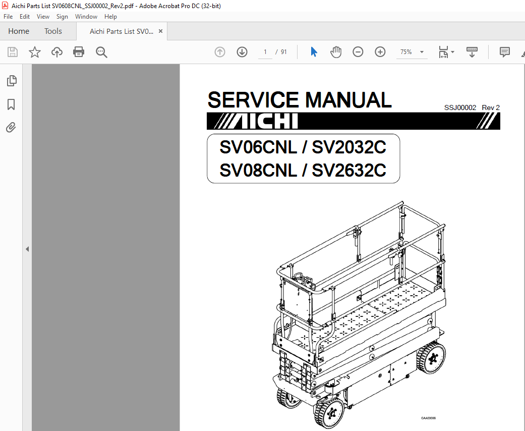
Aichi SV06CNL-SV2032C SV08CNL-SV2632C SERVICE MANUAL SSJ00002 – PDF DOWNLOAD
IMAGES PREVIEW OF THE MANUAL:
DESCRIPTION:
Aichi SV06CNL-SV2032C SV08CNL-SV2632C SERVICE MANUAL SSJ00002 – PDF DOWNLOAD
This manual describes correct adjustment and servicing procedures for Scissors
type self- propelled Elevation work platform: SV06CNL / SV2032C and
SV08CNL / SV2632C in order to ensure safe and reliable operation, the most
effective use of superb performance and excellent features for your satisfaction.
A qualified personnel should read this manual carefully and understand the
descriptions correctly before making any repair or maintenance works.
Always be sure of the following items when conducting repair or maintenance
works.
Use only the spare parts approved by the manufacturer, particularly for load supporting
components (Structural components including chassis, scissor arms
and platform) and safety related components (Scheduled replacement parts
listed in the page 6-5).
Use proper tools, lifting equipment and suitable workshop.
It is strictly forbidden to make modifications to the machine without obtaining
AICHI’s written approval.
Constant improvement of its products is
Constant improvement of its products is AICHI’s policy.
Therefore, specifications of the machine are subject to change without prior
notice.
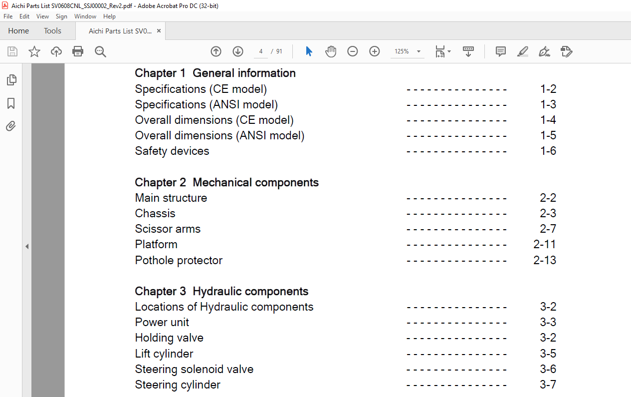
TABLE OF CONTENTS:
Aichi SV06CNL-SV2032C SV08CNL-SV2632C SERVICE MANUAL SSJ00002 – PDF DOWNLOAD
Chapter A
Introduction a
Safety warnings b
Chapter 1 General information
Specifications (CE model) 1-2
Specifications (ANSI model) 1-3
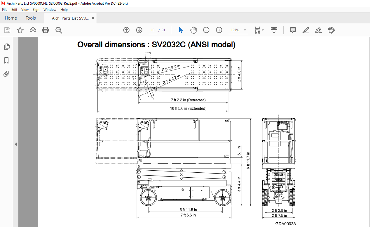
Overall dimensions (CE model) 1-4
Overall dimensions (ANSI model) 1-5
Safety devices 1-6
Chapter 2 Mechanical components
Main structure 2-2
Chassis 2-3
Scissor arms 2-7
Platform 2-11
Pothole protector 2-13
Chapter 3 Hydraulic components
Locations of Hydraulic components 3-2
Power unit 3-3
Holding valve 3-2
Lift cylinder 3-5
Steering solenoid valve 3-6
Steering cylinder 3-7
Chapter 4 Electric components
Locations of Electric components 4-2
Upper control box 4-3
Joystick controller 4-7
Steering dial (for Optional proportional steering) 4-8
Lower control box 4-9
Key switch 4-11
CPU board M6 4-12
Inverter unit 4-14
i i SSJ00002
Index
Pressure sensor (CE, Japan model) 4-16
Platform height sensor (ANSI, Japan model) /
Steering angle sensor 4-17
Platform height sensor (CE model) 4-18
Tilt sensor A (ANSI, Japan model) 4-19
Tilt sensor A and B (CE model) 4-20
Tilt sensor C 4-21
Travel motor 4-22
Electric magnetic brake 4-23
Battery charger 4-25
Battery disconnect switch 4-26
Chapter 5 Trouble shooting 5-2
Emergency operations 5-5
Chapter 6 Scheduled maintenance
Scheduled inspection table 6-2
Lubrication 6-4
Scheduled replacement parts 6-5
Daily inspection sheet 6-6
Periodical inspection sheet 6-7
Chapter 7 Appendix
Hydraulic circuit diagram 7-2
Electric circuit diagram 7-3
Electric wiring diagram 7-4
Battery cable arrangement 7-6
Water proof connector 7-7
Color code of Wires 7-9
Tightening torque standard 7-10
Trouble shooting by LED indication on Upper /
Lower control box
VIDEO PREVIEW OF THE MANUAL:
PLEASE NOTE:
- This is the same manual used by the dealers to diagnose and troubleshoot your vehicle
- You will be directed to the download page as soon as the purchase is completed. The whole payment and downloading process will take anywhere between 2-5 minutes
- Need any other service / repair / parts manual, please feel free to contact [email protected] . We still have 50,000 manuals unlisted
I.G


