

Aichi SR-210 SERVICE MANUAL SME-113 – PDF DOWNLOAD
IMAGES PREVIEW OF THE MANUAL:

DESCRIPTION:
Aichi SR-210 SERVICE MANUAL SME-113 – PDF DOWNLOAD
for SR-2 /0 self propelled aerial platform.
These procedures will ensure the most effective use of the operation features,
and will ensure satisfaction through excellent performance.
Read this manual carefully,
and ensure you understand each descriptions correctly.
When carrying out any maintenance or repair work,
please carefully note the following.
*Use only the spare parts approved by the manufacturer,
particularly for load-supporting and safety-related components.
*Do not carry out any modification to the machine
without obtaining the manufacturer’s approval.
Please note that the numerical values in this manual
may be subject to change due to engineering improvement.
TABLE OF CONTENTS:
Aichi SR-210 SERVICE MANUAL SME-113 – PDF DOWNLOAD
GENERAL INFORMATION
OVERALL DIMENSIONS 1 2
SPECIFICATIONS 1 4
WORKING RANGE CHART I b
MECHANICAL SECTION
BOOM 2 2
) Sectional drawings 2 3
2 Inspection procedures 2 4
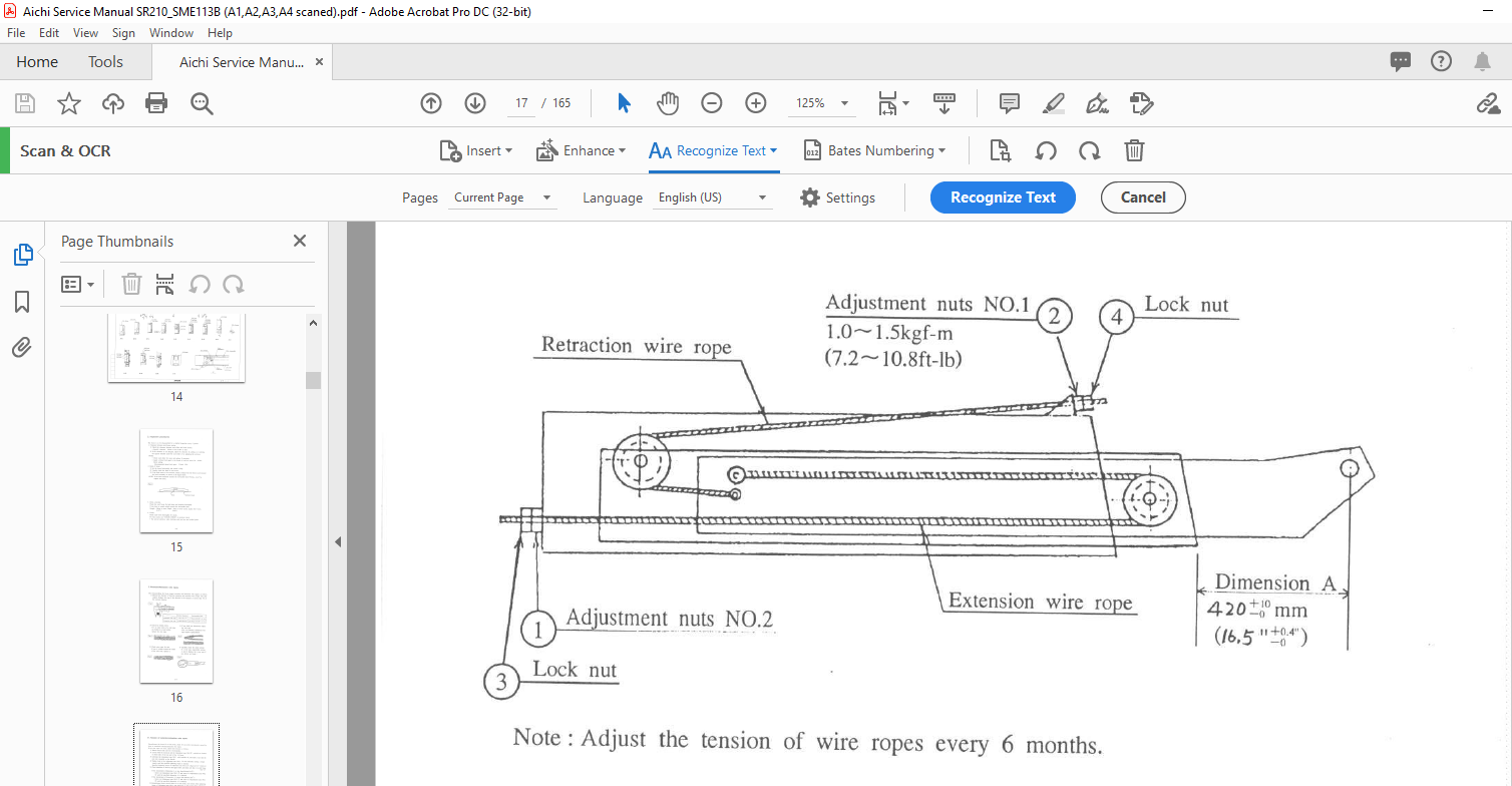
3 Extension/Retraction wire ropes 2 5
4 Tension of Extension/Retraction wire ropes 2 6
5 Tension of Electric cable 2 7
T T B (Turn Table Bearing) 2 8
PLATFORM SWING MECHANISM 2 10
HYDRAULIC SECTION
NOTE ON OVERHAULING HYDRAULIC SYSTEM 3 2
HYDRAULIC OIL 3 3
OIL RESERVOIR 3 5
IN LINE FILTER 3 6
HYDRAULIC PUMP 3 7
MAIN CONTROL VALVE NO l and NO 2 3 8
I Illustrations 3 9
2 Sectional drawings 3 10
3 Trouble shooting 3 1 1
PLATFORM SWING SOLENOID VALVE 3 12
PRIORITY VALVE 3 13
SWIVEL JOINT 3 14
ROTATION MOTOR UNIT 3 15
ELEVATION CYLINDER 3 16
SINGLE HOLDING VALVE(for Elevation cylinder) 3 17
Inspection procedures 3 18
EXTENSION CYLINDER 3 20
DOUBLE HOLDING VAL VE (for Extension cylinder) 3 21
Inspection procedures 3 22
PLATFORM LEVELLING SYSTEM 3 23
l Note on function 3 24
2 Inspection procedures 3 24
3 Adjustment of Platform level 3 25
4 Air bleeding procedu res 3 26
LOWER LEVELLING CYLINDER 3 27
UPPER LEVELLING CYLINDER 3 28
DOUBLE PILOT CHECK VAL VE (for Upper levelling cylinder) 3 29
CON BIN A TION VAL VE (for Platform levelling system) 3 30
PLATFORM Lf=VE:L 50t E Nor D VALVE 3 31
f)OUBLE PlLDT CHE CJ< VALVE (FPr P/atfbY/n /eve//in; s7~fTe,,r ) 3 P
PLATFORM LEVEL SOLENOID VALVE 3 _31
DOUBLE PILOT CHECK VALVE 3 32
ELECTRIC SECTION
UPPEER CONTROL BOX 4 2
1 Electric circuit 4 3
RELAY BOX 4 5
LOWER CONTROL BOX 4 6
1 Elect r i c circuit 4 7
MAIN KEY SWITCH 4 8
INTERFACE BOARD • 4 9
1 Elect r i c circuit 4 10
CPU BOARD • 4 11
l Not e on function of CPU board (NO I) 4 12
2 Not e on function of CPU board (NO 2) 4 13
VALVE CONTROL UNIT 4 14
1 Specification 4 14
2 Input /Out put charact erist ic 4 14
3 Ext ernal view 4 14
4 Funct ion of Valve cont rol unit 4 15
5 Funct ion of Trimmers and LEDs 4 16
FUNCTION OF LOWER CONTROL BOX 4 17
BOOM ANGLE and LENGTH SENSORS 4 18
ACCELERATOR MOTOR • 4 19
1 Electric circuit • 4 20
2 Inspect ion 4 20
SLOPE SENSOR 4 21
FOOT SWITCH 4 2 2
FUEL LEVEL SEN SOR • 4 2 3
ELECTRIC COMPONENTS at t ached on ENGINE • 4 24
I Engine st op solenoid 4 24
2 Glow indicator 4 24
3 St art er mot or 4 25
4 Safet y relay 4 26
5 Alt ernat or •• 4 27
6 Bat t ery relay 4 28
ELECTRIC CIRCUIT FOR INDIVIDUAL SYSTEM
ENGINE CONTROL SYSTEM 5 2
ROTATION SYSTEM • 5 3
EXTENSION SYSTEM 5 4
ELEVATION SYSTEM 5 5
TRAVEL (RIGHT) SYSTEM 5 6
TRAVEL (LEFT) SYSTEM 5 7
ACCELERATOR SYSTEM 5 8
PLATFORM SWING and PLATFORM LEVEL SYSTEM 5 9
SLOPE WARNING,HORN and WORKING LIGHT SYSTEM 5 10
MOTION ALARM SYSTEM 5 11
EMERGENCY PUMP SYSTEM 5 12
ADJUSTMENT SECTION
RELIEF VALVE Pl and P4 6 2
RELIEF VALVE P2 • 6 3
RELIEF VALVE P3 6 4
OPERATIONAL SPEED 6 5
I Measurement procedures of
“Maximum operational speed” 6 6
2 Adjustment procedures of “Operational speed” 6 7
ADJUSTMENT of CPU BOARD 6 12
I Calibration of Boom angle and length sensors 6 13
2 Adjustment of Limited rotation speed” 6 13
3 Adjustment of Limited elevation speed” 6 14
4 Adjustment of Limited travel speed” 6 15
5 Adjustment of Stroke end shockless range” 6 16
6 Adjustment of Pivot turn speed” 6 17
7 Adjustment of Spin turn speed” 6 18
ADJUSTMENT DATA SHEET 6 19
APPENDIX
TROUBLE SHOOTING 7 2
Identifications of “Control devices” and “Fuses” 7 4
HYDRAULIC CIRCUIT DIAGRAM 7 5
IDENTIFICATIONS OF HYDRAULIC COMPONENTS 7 6
ELECTRIC CIRCUIT DIAGRAM 7 7
IDENTIFICATION OF ELECTRIC COMPONENTS 7 8
TIGHTENING TORQUE STANDARD 7 9
INSPECTION MANUAL
PROCEDURES OF DAILY INSPECTION
DAILY INSPECTION CHECK SHEET
PROCEDURES OF PERIODICAL INSPECTION
8 1
8 3
8 5
PROCEDURES OF FUNCTION TEST 8 11
PERIODICAL INSPECTION CHECK SHEET 8 12
VIDEO PREVIEW OF THE MANUAL:
PLEASE NOTE:
- This is the SAME MANUAL used by the dealerships to diagnose your vehicle
- No waiting for couriers / posts as this is a PDF manual and you can download it within 2 minutes time once you make the payment.
- Your payment is all safe and the delivery of the manual is INSTANT – You will be taken to the DOWNLOAD PAGE.
- So have no hesitations whatsoever and write to us about any queries you may have : heydownloadss @gmail.com
I.G


