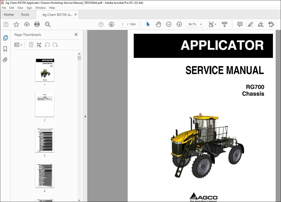
Ag Chem RG700 Applicator Chassis Service Manual_79035584A – PDF DOWNLOAD
Original price was: $86.95.$36.95Current price is: $36.95.
Ag Chem RG700 Applicator Chassis Service Manual_79035584A – PDF DOWNLOAD
Description
Ag Chem RG700 Applicator Chassis Service Manual_79035584A – PDF DOWNLOAD
FILE DETAILS:
Ag Chem RG700 Applicator Chassis Service Manual_79035584A – PDF DOWNLOAD
Language : English
Pages : 1844
Downloadable : Yes
File Type : PDF
Size: 179 MB
IMAGES PREVIEW OF THE MANUAL:
DESCRIPTION:
Ag Chem RG700 Applicator Chassis Service Manual_79035584A – PDF DOWNLOAD
SERVICE MANUAL:
This service manual has been prepared with the latest service information available at the time of publication. Read the service manual carefully before doing any service on the machine.
- Right-hand and left-hand, as used in this manual, is determined by facing the direction the machine will travel when in use.
- The photos, illustrations, and data used in this manual were current at the time of printing, but due to possible production change, your machine can vary slightly. The Manufacturer reserves the right to redesign and change the machine as necessary without notification.
UNITS OF MEASUREMENT:
Measurements are given in metric units of measurement followed by the equivalent in U.S. units. Hardware sizes are given in millimeters for metric hardware and inches for U.S. hardware.
REPLACEMENT PARTS:
To receive prompt efficient service, always remember to have the following information:
• Correct part description and part number.
• Model number of your machine.
• Serial number of your machine.
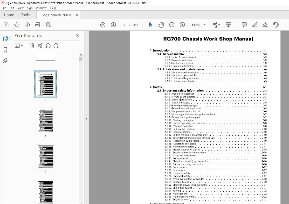
TABLE OF CONTENTS:
Ag Chem RG700 Applicator Chassis Service Manual_79035584A – PDF DOWNLOAD
1 Introduction 1-1
1 1 Service manual 1-3
1 1 1 Units of measurement 1-3
1 1 2 Replacement parts 1-3
1 1 3 Identification plates 1-3
1 1 4 Engine identification 1-5
1 2 Lubrication and maintenance 1-6
1 2 1 Maintenance introduction 1-6
1 2 2 Maintenance schedule 1-6
1 2 3 Lubricant filling reminders 1-9
1 2 4 Lubricants and fluids 1-9
2 Safety 2-1
2 1 Important safety information 2-3
2 1 1 Prepare for operation 2-3
2 1 2 A word to the operator 2-3
2 1 3 Safety alert symbol 2-4
2 1 4 Safety messages 2-5
2 1 5 Informational messages 2-5
2 1 6 General hazard information 2-5
2 1 7 Fire prevention and first aid 2-6
2 1 8 Mounting and dismounting the machine 2-7
2 1 9 Before starting the engine 2-7
2 1 10 Starting the engine 2-8
2 1 11 Before operating the machine 2-8
2 1 12 Machine operation 2-8
2 1 13 Parking the machine 2-10
2 1 14 Operator station 2-10
2 1 15 Exiting the cab in an emergency 2-10
2 1 16 Safety lamps and marking devices use 2-10
2 1 17 Roading on public roads 2-10
2 1 18 Operating on a slope 2-11
2 1 19 Maintenance safety 2-11
2 1 20 Proper disposal of waste 2-15
2 1 21 Support the machine correctly 2-15
2 1 22 Asbestos information 2-16
2 1 23 Pressurized air 2-16
2 1 24 Electrical storm injury prevention 2-16
2 1 25 Cut and crushing prevention 2-16
2 1 26 Boom safety 2-17
2 1 27 Fuel safety 2-17
2 1 28 Hydraulic safety 2-17
2 1 29 Chemical safety 2-17
2 1 30 Avoid eye contact with radar 2-20
2 1 31 Exhaust fumes 2-20
2 1 32 Electrical power lines overhead 2-21
2 1 33 Shield and guards 2-21
2 1 34 Towing 2-22
2 1 35 Modifications 2-22
2 1 36 High pressure leaks 2-22
2 1 37 Engine safety 2-23
RG700 Chassis Work Shop Manual
79035584 A Rev
Table of contents
2 1 38 Battery safety 2-25
2 1 39 Tire safety 2-25
2 1 40 Mobile radio installation 2-26
2 1 41 Safety signs 2-26
2 2 Tightening specifications 2-27
2 2 1 Constant torque hose clamp 2-27
2 2 2 Fastener tightening specifications 2-27
2 2 3 Metric fasteners 2-30
2 2 4 Inch fasteners 2-31
2 2 5 Conversion table 2-35
3 Engine 3-1
3 1 Serpentine belt replacement 3-3
3 1 1 Removing the main serpentine belt 3-3
3 1 2 Installing the main serpentine belt 3-5
3 2 Alternator replacement 3-8
3 2 1 Removing the bottom alternator 3-8
3 2 2 Installing the bottom alternator 3-1 0
3 2 3 Removing the top alternator 3-12
3 2 4 Installing the top alternator 3-15
3 3 Cooling package 3-19
3 3 1 Removing the cooling package 3-19
3 3 2 Disassembling the cooling package 3-27
3 3 3 Assembling the cooling package 3-33
3 3 4 Installing the cooling package 3-40
3 4 Radiator core 3-49
3 4 1 Removing the radiator core 3-49
3 4 2 Installing the radiator core 3-56
3 5 Hydraulic oil cooler 3-63
3 5 1 Removing the hydraulic oil cooler 3-63
3 5 2 Installing the hydraulic oil cooler 3-67
3 6 Air conditioner condenser/ fuel cooler 3-72
3 6 1 Removing the air conditioning condenser/fuel cooler 3-72
3 6 2 Installing air conditioning condenser and fuel cooler 3-75
3 7 Charge air cooler 3-78
3 7 1 Removing the charge air cooler 3-78
3 7 2 Installing the charge air cooler 3-84
3 8 Air filter assembly 3-91
3 8 1 Removing the air filter assembly 3-91
3 8 2 Installing the air filter assembly 3-96
3 9 Air filters 3-101
3 9 1 Removing the air filters 3-101
3 9 2 Installing the air filters 3-103
3 10 Exhaust system 3-107
3 10 1 Removing the exhaust system 3-107
3 10 2 Installing the exhaust system 3-113
3 11 Batteries 3-118
3 11 1 Removing the batteries 3-118
3 11 2 Installing the batteries 3-120
3 12 Fan 3-124
3 12 1 Removing the fan 3-124
3 12 2 Installing the fan 3-127
3 13 Air conditioning compressor 3-130
3 13 1 Removing the air conditioning compressor 3-130
RG700 Chassis Work Shop Manual
79035584 A Rev
Table of contents
3 13 2 Installing the air conditioning compressor 3-133
3 14 Air conditioning receiver/ dryer 3-138
3 14 1 Removing the air conditioning receiver-dryer 3-138
3 14 2 Installing the air conditioning receiver-dryer 3-140
3 15 Engine cover 3-143
3 15 1 Removing the engine cover 3-143
3 15 2 Disassembling the engine cover 3-147
3 15 3 Assembling the engine cover 3-152
3 15 4 Disassembling the headlamp 3-157
3 15 5 Assembling the headlamp 3-157
3 15 6 Installing the engine cover 3-158
3 15 7 Adjusting the engine cover 3-162
3 16 Air compressor 3-165
3 16 1 Removing the air compressor 3-165
3 16 2 Installing the air compressor 3-169
3 17 Starter 3-174
3 17 1 Removing the starter 3-174
3 17 2 Installing the starter 3-175
3 18 Engine 3-178
3 18 1 Removing the engine 3-178
3 18 2 Installing the engine 3-197
3 19 Pump drive flange 3-215
3 19 1 Removing the pump drive flange 3-215
3 19 2 Installing the pump drive flange 3-216
3 20 Engine mounts 3-217
3 20 1 Removing the engine mounts 3-217
3 20 2 Installing the engine mounts 3-218
3 21 Engine fittings 3-219
3 21 1 Removing the engine fittings 3-219
3 21 2 Installing the engine fittings 3-220
3 22 Diesel exhaust fluid 3-221
3 22 1 Removing the diesel exhaust fluid 3-221
3 22 2 Disassembling the diesel exhaust fluid tank 3-230
3 22 3 Assembling the diesel exhaust fluid tank 3-231
3 22 4 Installing the diesel exhaust fluid 3-232
3 23 Fuel line 3-241
3 23 1 Removing the fuel line 3-241
3 23 2 Installing the fuel line 3-244
3 24 Pre fuel filter / water separator 3-249
3 24 1 Removing the pre fuel filter 3-249
3 24 2 Installing the pre-fuel filter 3-250
3 25 Opt fuel filter/ water separator 3-253
3 25 1 Removing the fuel filter water separator 3-253
3 25 2 Installing the fuel filter water separator 3-255
3 25 3 Backflushing fuel filter water separator 3-257
3 26 Operating the fuel priming pump 3-261
3 27 Fuel filter 3-264
3 27 1 Removing the fuel filter 3-264
3 27 2 Installing the fuel filter 3-265
3 28 Fuel specifications 3-267
3 29 Coolant specification 3-268
3 30 Oil specification 3-269
4 Cab and platform 4-1
RG700 Chassis Work Shop Manual
79035584 A Rev
Table of contents
4 1 Removing and installing the cab 4-3
4 1 1 Removing the cab 4-3
4 1 2 Installing the cab 4-6
4 2 Cab filtration 4-1 o
4 2 1 General Information 4-10
4 3 Cab seat 4-15
4 3 1 Removing the seat 4-1 5
4 3 2 Installing the seat 4-16
4 4 Rogator management center 4-19
4 4 1 Removing the RMC 4-19
4 4 2 Installing the RMC 4-20
4 5 Cab components 4-23
4 5 1 Removing the switches 4-23
4 5 2 Installing the switches 4-24
4 5 3 Removing the steering console 4-24
4 5 4 Installing the steering console 4-27
4 6 Heating, ventilation, air conditioning and cooling 4-29
4 6 1 System operation 4-29
4 6 2 HVAC system 4-30
4 6 3 Electronic HVAC controls 4-30
4 6 4 Pressurizing the cab 4-30
4 6 5 Removing moisture from the cab airflow 4-30
4 6 6 Circulation of the cab airflow 4-30
4 6 7 Heating the cab airflow 4-30
4 6 8 Cooling the cab airflow 4-31
4 6 9 Refrigerant system sensors 4-31
4 6 10 Pumping 4-31
4 6 11 Compression ( Discharge side) 4-31
4 6 12 Temperature control switch 4-31
4 7 Testing and adjusting 4-32
4 7 1 Troubleshooting machine preparation 4-32
4 7 2 General troubleshooting information 4-32
4 7 3 Automatic temperature control panel test 4-33
4 7 4 Troubleshooting faults with service codes 4-34
4 7 5 Entering advanced diagnostics 4-35
4 7 6 Troubleshooting using advanced diagnostics 4-35
4 8 Basic air conditioning system testing 4-38
4 8 1 Visual inspection 4-38
4 8 2 Verifying the system failure 4-38
4 9 Checking the system pressure 4-39
4 9 1 Manifold gauge set 4-39
4 9 2 Installing the manifold gauge 4-39
4 9 3 Using the manifold gauge test 4-40
4 9 4 Check the air temperature 4-40
4 9 5 Evaluating the data 4-41
4 9 6 Pressure-temperature chart 4-41
4 9 7 Base line performance test 4-41
4 9 8 Recovering refrigerant 4-42
4 9 9 Refrigerant contamination 4-42
4 9 10 Recovery 4-42
4 9 11 Moisture in a refrigerant system 4-43
4 9 12 Results of pressure on water boiling points 4-43
4 9 13 Boiling temperature of water at converted pressures 4-44
4 9 14 Before evacuation 4-45
4 9 15 Evacuating the system 4-46
RG700 Chassis Work Shop Manual
79035584 A Rev
Table of contents
4 10 Refrigerant recovery 4-47
4 10 1 Refrigerant recovery tools 4-47
4 10 2 Recovering refrigerant 4-47
4 10 3 Flushing the refrigerant system 4-48
4 10 4 Testing a refrigerant leak using dye 4-48
4 10 5 Testing a refrigerant leak using a leak detector 4-48
4 10 6 Check the refrigerant compressor oil 4-49
4 10 7 Charging the refrigerant system 4-49
4 10 8 Charging the system 4-53
4 10 9 Charging the system with a scale 4-53
4 10 10 Adding additional refrigerant to a low charge 4-55
4 10 11 Removing the manifold gauge set 4-55
4 11 Handrail ladder and platform 4-57
4 11 1 Removing the handrail 4-57
4 11 2 Installing the handrail 4-60
4 11 3 Removing the ladder 4-62
4 11 4 Installing the ladder 4-67
4 11 5 Removing the platform 4-70
4 11 6 Installing the platform 4-72
5 Frame and axles 5-1
5 1 Chassis introduction 5-3
5 2 Front axle introduction 5-4
5 3 Front axle removal 5-5
5 3 1 Removing the front axle wheel leg 5-5
5 3 2 Removing the front steerable axle weldment 5-10
5 3 3 Removing the front axle weldment 5-15
5 3 4 Removing the front axle air spring 5-25
5 4 Front axle installation 5-28
5 4 1 Installing the front axle air spring 5-28
5 4 2 Installing the front axle weldment 5-29
5 4 3 Installing the front steerable axle weldment 5-38
5 4 4 Installing the front axle wheel leg 5-43
5 5 Rear axle introduction 5-49
5 6 Rear axle removal 5-50
5 6 1 Removing the rear inner axle weldment 5-50
5 6 2 Removing the rear axle weldment 5-56
5 6 3 Removing the rear axle air spring 5-65
5 7 Rear axle installation 5-68
5 7 1 Installing the rear axle air spring 5-68
5 7 2 Installing the rear axle weldment 5-69
5 7 3 Installing the rear inner axle weldment 5-77
5 8 Adjusting the toe-in 5-84
5 9 Wheels 5-86
5 9 1 Removing the wheel 5-86
5 9 2 Installing the wheel 5-87
5 9 3 Tightening the wheel mounting hardware 5-88
5 10 Air system components 5-89
5 10 1 Removing the air compressor 5-89
5 10 2 Installing the air compressor 5-94
5 10 3 Removing the regulator 5-98
5 10 4 Installing the regulator 5-99
5 10 5 Removing the air tank 5-100
5 10 6 Installing the air tank 5-102
5 10 7 Removing the pressure switch 5-105
RG700 Chassis Work Shop Manual
79035584 A Rev
Table of contents
5 10 8 Installing the pressure switch 5-105
5 10 9 Removing the ride height control valve 5-106
5 10 1 0 Installing the ride height control valve 5-108
5 10 11 Adjusting the ride height 5-11 0
5 10 12 Removing the front axle air spring 5-111
5 10 13 Installing the front axle air spring 5-112
5 10 14 Removing the rear axle air spring 5-114
5 10 15 Installing the rear axle air spring 5-116
5 10 16 Removing the air dump valve 5-117
5 10 17 Installing the air dump valve 5-118
5 11 Fender 5-121
5 11 1 Removing the fenders 5-121
5 11 2 Installing the fenders 5-122
5 11 3 Adjusting the fender vertical 5-124
5 11 4 Adjusting the fender horizontally 5-124
5 12 Crop deflector 5-126
5 12 1 Removing the crop deflector 5-126
5 12 2 Installing the crop deflector 5-127
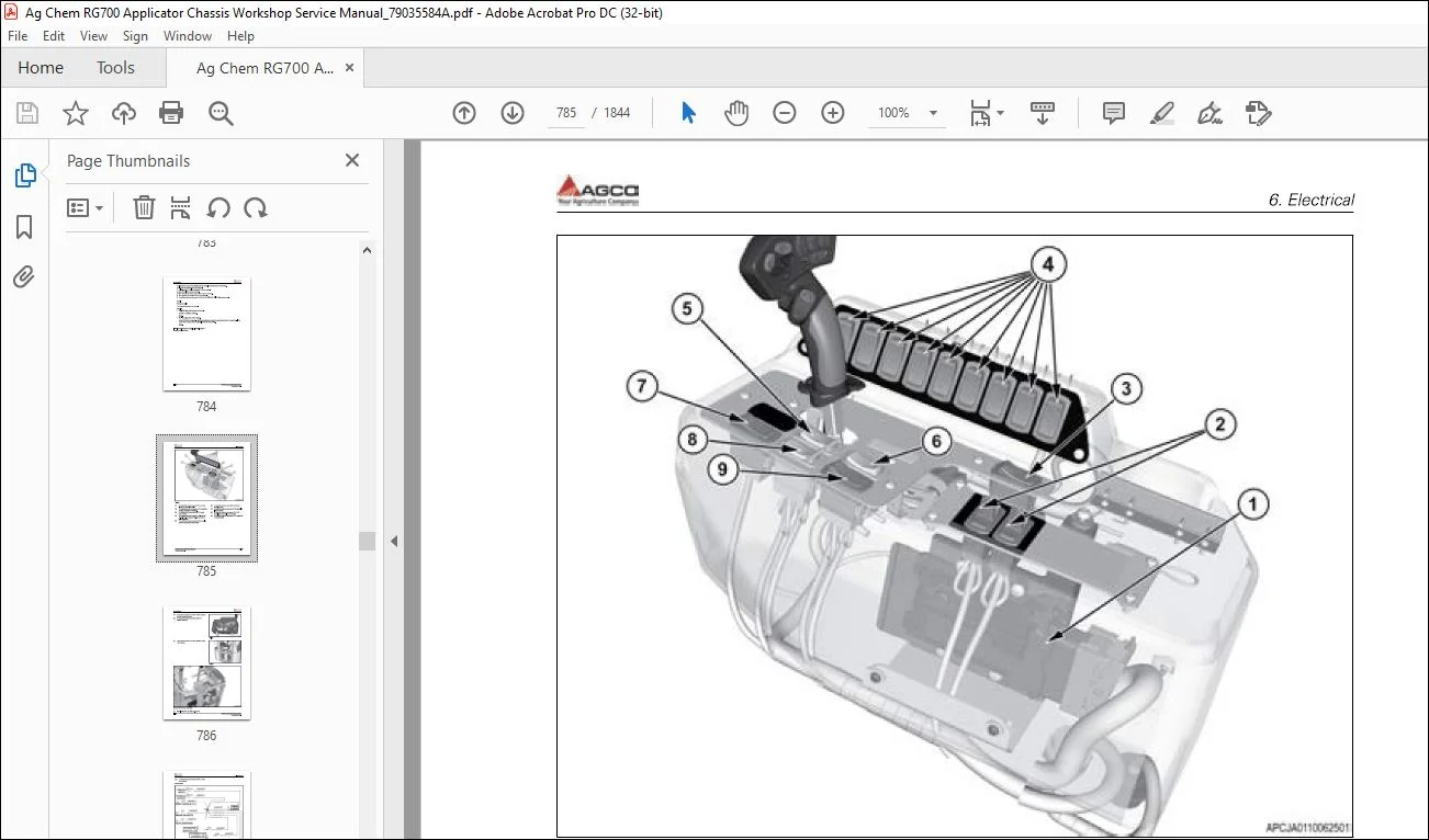
6 Electrical 6-1
6 1 Battery compartment components 6-7
6 1 1 Removing the battery compartment components 6-7
6 1 2 Installing the battery compartment components 6-11
6 1 3 Disassembling the power distribution panel 6-16
6 1 4 Assembling the power distribution panel 6-17
6 1 5 Disassembling the fuse/relay panel 6-18
6 1 6 Assembling the fuse and relay panel 6-19
6 1 7 Disassembling the light module panel 6-19
6 1 8 Assembling the light module panel 6-20
6 2 Failure mode indicator descriptions 6-22
6 2 1 Failure mode indicator (FMI) description 6-22
6 3 SA 00 Engine module 6-26
6 3 1 Code SA 00 SPN 1761 FMI 01 6-26
6 3 2 Code SA 00 SPN 1761 FM I 03 6-29
6 3 3 Code SA 00 SPN 3031 FMI 03 6-32
6 3 4 Code SA 00 SPN 3031 FMI 04 6-35
6 3 5 Code SA 00 SPN 3031 FMI 14 6-38
6 3 6 Code SA 00 SPN 3031 FMI 16 6-41
6 3 7 Code SA 00 SPN 3363 FMI 03 6-44
6 3 8 Code SA 00 SPN 3363 FMI 04 6-47
6 3 9 Code SA 00 SPN 3363 FMI 05 6-50
6 3 10 Code SA 00 SPN 3363 FM I 31 6-53
6 3 11 Code SA 00 SPN 4334 FMI 03 6-56
6 3 12 Code SA 00 SPN 4334 FMI 04 6-59
6 3 13 Code SA 00 SPN 4340 FMI 03 6-62
6 3 14 Code SA 00 SPN 4340 FMI 04 6-65
6 3 15 Code SA 00 SPN 4340 FMI 05 6-70
6 3 16 Code SA 00 SPN 4340 FMI 31 6-75
6 3 17 Code SA 00 SPN 4342 FMI 03 6-77
6 3 18 Code SA 00 SPN 4342 FMI 04 6-79
6 3 19 Code SA 00 SPN 4342 FMI 05 6-81
6 3 20 Code SA 00 SPN 4342 FMI 31 6-83
6 3 21 Code SA 00 SPN 4344 FMI 02 6-85
6 3 22 Code SA 00 SPN 4344 FMI 03 6-87
6 3 23 Code SA 00 SPN 4344 FMI 04 6-89
6 3 24 Code SA 00 SPN 4344 FMI 08 6-91
RG700 Chassis Work Shop Manual
79035584 A Rev
Table of contents
6 3 25 Code SA 00 SPN 4344 FM I 12 6-93
6 3 26 Code SA 00 SPN 4344 FMI 31 6-95
6 3 27 Code SA 00 SPN 4346 FM I 03 6-97
6 3 28 Code SA 00 SPN 4346 FM I 04 6-99
6 3 29 Code SA 00 SPN 4346 FMI 31 6-101
6 3 30 Code SA 00 SPN 4354 FM I 04 6-103
6 3 31 Code SA 00 SPN 4354 FMI 03 6-105
6 3 32 Code SA 00 SPN 4355 FM I 03 6-107
6 3 33 Code SA 00 SPN 4355 FM I 04 6-109
6 3 34 Code SA 00 SPN 4356 FM I 03 6-111
6 3 35 Code SA 00 SPN 4357 FM I 03 6-113
6 3 36 Code SA 00 SPN 4357 FM I 04 6-115
6 3 37 Code SA 00 SPN 4357 FM I 05 6-117
6 3 38 Code SA 00 SPN 4376 FM I 03 6-119
6 3 39 Code SA 00 SPN 4376 FM I 04 6-121
6 3 40 Code SA 00 SPN 4376 FM I 05 6-123
6 3 41 Code SA 00 SPN 4376 FM I 31 6-125
6 3 42 Code SA 00 SPN 521000 FMI 02 6-127
6 3 43 Code SA 00 SPN 521000 FMI 08 6-129
6 3 44 Code SA 00 SPN 521001 FMI 03 6-131
6 3 45 Code SA 00 SPN 521001 FMI 04 6-133
6 3 46 Code SA 00 SPN 521001 FMI 31 6-135
6 3 47 Code SA 00 SPN 521002 FMI 03 6-137
6 3 48 Code SA 00 SPN 521002 FMI 04 6-139
6 3 49 Code SA 00 SPN 521 002 FM I 05 6-141
6 3 50 Code SA 00 SPN 521002 FMI 31 6-143
6 3 51 Code SA 00 SPN 521003 FMI 03 6-145
6 3 52 Code SA 00 SPN 521003 FMI 04 6-147
6 3 53 Code SA 00 SPN 521004 FMI 02 6-149
6 3 54 Code SA 00 SPN 521004 FMI 11 6-151
6 3 55 Code SA 00 SPN 521004 FMI 12 6-153
6 3 56 Code SA 00 SPN 521005 FMI 02 6-155
6 3 57 Code SA 00 SPN 521005 FMI 11 6-157
6 3 58 Code SA 00 SPN 521005 FMI 12 6-159
6 3 59 Code SA 00 SPN 521006 FMI 12 6-161
6 3 60 Code SA 00 SPN 521007 FMI 10 6-163
6 3 61 Code SA 00 SPN 521007 FMI 14 6-166
6 3 62 Code SA 00 SPN 521007 FMI 31 6-169
6 3 63 Code SA 00 SPN 521008 FMI 00 6-172
6 3 64 Code SA 00 SPN 521008 FMI 01 6-175
6 4 SA 05 Armrest module 6-180
6 4 1 Code SA 05 SPN 898 FM I 03 6-180
6 4 2 Code SA 05 SPN 898 FMI 04 6-184
6 4 3 Code SA 05 SPN 1865 FM I 02 6-190
6 4 4 Code SA 05 SPN 2347 FMI 02 6-200
6 4 5 Code SA 05 SPN 2349 FMI 02 6-205
6 4 6 Code SA 05 SPN 2367 FMI 02 6-210
6 4 7 Code SA 05 SPN 2369 FMI 02 6-214
6 4 8 Code SA 05 SPN 2403 FMI 02 6-219
6 4 9 Code SA 05 SPN 2858 FMI 02 6-225
6 4 10 Code SA 05 SPN 3509 FMI 03 6-227
6 4 11 Code SA 05 SPN 3509 FMI 04 6-237
6 4 12 Code SA 05 SPN 3511 FMI 03 6-248
6 4 13 Code SA 05 SPN 3511 FMI 04 6-257
6 4 14 Code SA 05 SPN 3646 FM I 03 6-266
6 4 15 Code SA 05 SPN 3646 FMI 04 6-271
6 4 16 Code SA 05 SPN 522063 FMI 03 6-276
RG700 Chassis Work Shop Manual
79035584 A Rev
Table of contents
6 4 17 Code SA 05 SPN 522063 FMI 04 6-281
6 4 18 Code SA 05 SPN 522064 FMI 03 6-286
6 4 19 Code SA 05 SPN 522064 FMI 04 6-291
6 4 20 Code SA 05 SPN 522065 FMI 03 6-296
6 4 21 Code SA 05 SPN 522065 FMI 04 6-301
6 4 22 Code SA 05 SPN 522066 FMI 03 6-306
6 4 23 Code SA 05 SPN 522066 FMI 04 6-311
6 4 24 Code SA 05 SPN 522067 FMI 03 6-316
6 4 25 Code SA 05 SPN 522067 FMI 04 6-321
6 4 26 Code SA 05 SPN 522068 FMI 03 6-326
6 4 27 Code SA 05 SPN 522068 FMI 04 6-331
6 4 28 Code SA 05 SPN 522069 FMI 03 6-336
6 4 29 Code SA 05 SPN 522069 FMI 04 6-341
6 4 30 Code SA 05 SPN 522070 FMI 03 6-346
6 4 31 Code SA 05 SPN 522070 FMI 04 6-349
6 4 32 Code SA 05 SPN 522079 FMI 03 6-354
6 4 33 Code SA 05 SPN 522079 FMI 04 6-360
6 4 34 Code SA 05 SPN 522080 FMI 03 6-366
6 4 35 Code SA 05 SPN 522080 FMI 04 6-371
6 4 36 Code SA 05 SPN 522087 FMI 03 6-377
6 4 37 Code SA 05 SPN 522087 FMI 04 6-381
6 4 38 Code SA 05 SPN 522104 FMI 05 6-385
6 4 39 Code SA 05 SPN 522104 FMI 06 6-395
6 4 40 Code SA 05 SPN 522158 FMI 31 6-406
6 4 41 Code SA 05 SPN 522159 FMI 31 6-410
6 4 42 Code SA 05 SPN 522160 FMI 31 6-415
6 4 43 Code SA 05 SPN 522174 FMI 13 6-420
6 4 44 Code SA 05 SPN 522176 FMI 31 6-421
6 4 45 Code SA 05 SPN 522178 FMI 03 6-422
6 4 46 Code SA 05 SPN 522178 FMI 04 6-427
6 4 47 Code SA 05 SPN 522179 FMI 03 6-432
6 4 48 Code SA 05 SPN 522179 FMI 04 6-437
6 4 49 Code SA 05 SPN 522180 FMI 03 6-443
6 4 50 Code SA 05 SPN 522180 FMI 04 6-447
6 5 SA 46 Hydrostatic drive pump module 6-454
6 5 1 Code SA 46 SPN 300719 FM I 8 6-454
6 5 2 Code SA 46 SPN 300721 FMI 31 6-455
6 5 3 Code SA 46 SPN 300722 FMI 31 6-462
6 5 4 Code SA 46 SPN 300723 FMI 31 6-468
6 5 5 Code SA 46 SPN 300724 FMI 31 6-474
6 5 6 Code SA 46 SPN 300731 FMI 31 6-480
6 5 7 Code SA 46 SPN 300732 FMI 31 6-486
6 5 8 Code SA 46 SPN 300749 FMI 31 6-492
6 5 9 Code SA 46 SPN 300750 FMI 05 6-498
6 5 10 Code SA46 SPN 300751 FMI 05 6-504
6 5 11 Code SA 46 SPN 300752 FMI 06 6-510
6 5 12 Code SA46 SPN 300753 FMI 06 6-516
6 5 13 Code SA 46 SPN 300754 FMI 06 6-522
6 5 14 Code SA46 SPN 300755 FMI 06 6-528
6 5 15 Code SA 46 SPN 300756 FMI 06 6-534
6 5 16 Code SA 46 SPN 300757 FMI 06 6-540
6 5 17 Code SA 46 SPN 300758 FMI 05 6-546
6 5 18 Code SA 46 SPN 300759 FMI 05 6-552
6 5 19 Code SA46 SPN 300764 FMI 31 6-558
6 6 SA 192 System module 6-559
6 6 1 Code SA 192 SPN 2368 FMI 05 6-559
6 6 2 Code SA 192 SPN 2368 FMI 06 6-562
RG700 Chassis Work Shop Manual
79035584 A Rev
Table of contents
6 6 3 Code SA 192 SPN 2370 FMI 06 6-565
6 6 4 Code SA 192 SPN 2372 FMI 05 6-568
6 6 5 Code SA 192 SPN 2372 FMI 06 6-571
6 6 6 Code SA 192 SPN 2374 FMI 05 6-575
6 6 7 Code SA 192 SPN 2374 FMI 06 6-578
6 6 8 Code SA 192 SPN 2392 FMI 05 6-582
6 6 9 Code SA 192 SPN 2404 FMI 05 6-585
6 6 10 Code SA 192 SPN 2404 FMI 06 6-589
6 6 11 Code SA 192 SPN 522020 FMI 05 6-592
6 6 12 Code SA 192 SPN 522020 FMI 06 6-595
6 6 13 Code SA 192 SPN 522021 FMI 05 6-598
6 6 14 Code SA 192 SPN 522021 FMI 06 6-601
6 6 15 Code SA 192 SPN 522022 FMI 05 6-604
6 6 16 Code SA 192 SPN 522022 FMI 06 6-607
6 6 17 Code SA 192 SPN 522023 FMI 05 6-610
6 6 18 Code SA 192 SPN 522023 FMI 06 6-613
6 6 19 Code SA 192 SPN 522024 FMI 05 6-616
6 6 20 Code SA 192 SPN 522024 FMI 06 6-619
6 6 21 Code SA 192 SPN 522025 FMI 05 6-622
6 6 22 Code SA 192 SPN 522025 FMI 06 6-625
6 6 23 Code SA 192 SPN 522026 FMI 05 6-628
6 6 24 Code SA 192 SPN 522026 FMI 06 6-631
6 6 25 Code SA 192 SPN 522027 FMI 05 6-634
6 6 26 Code SA 192 SPN 522027 FMI 06 6-637
6 6 27 Code SA 192 SPN 522028 FMI 05 6-640
6 6 28 Code SA 192 SPN 522028 FMI 06 6-643
6 6 29 Code SA 192 SPN 522029 FMI 05 6-646
6 6 30 Code SA 192 SPN 522029 FMI 06 6-649
6 6 31 Code SA 192 SPN 522030 FMI 05 6-652
6 6 32 Code SA 192 SPN 522030 FMI 06 6-655
6 6 33 Code SA 192 SPN 522031 FMI 05 6-658
6 6 34 Code SA 192 SPN 522031 FMI 06 6-661
6 6 35 Code SA 192 SPN 522032 FMI 05 6-664
6 6 36 Code SA 192 SPN 522032 FMI 06 6-668
6 6 37 Code SA 192 SPN 522033 FMI 05 6-672
6 6 38 Code SA 192 SPN 522033 FMI 06 6-676
6 6 39 Code SA 192 SPN 522037 FMI 05 6-680
6 6 40 Code SA 192 SPN 522037 FMI 06 6-684
6 6 41 Code SA 192 SPN 522038 FMI 05 6-688
6 6 42 Code SA 192 SPN 522038 FMI 06 6-692
6 6 43 Code SA 192 SPN 522039 FMI 05 6-696
6 6 44 Code SA 192 SPN 522039 FMI 06 6-700
6 6 45 Code SA 192 SPN 522040 FMI 05 6-703
6 6 46 Code SA 192 SPN 522040 FMI 06 6-707
6 6 47 Code SA 192 SPN 522041 FMI 05 6-710
6 6 48 Code SA 192 SPN 522041 FMI 06 6-714
6 6 49 Code SA 192 SPN 522042 FMI 05 6-717
6 6 50 Code SA 192 SPN 522042 FMI 06 6-721
6 6 51 Code SA 192 SPN 522043 FMI 05 6-724
6 6 52 Code SA 192 SPN 522043 FMI 06 6-728
6 6 53 Code SA 192 SPN 522044 FMI 05 6-731
6 6 54 Code SA 192 SPN 522044 FMI 06 6-735
6 6 55 Code SA 192 SPN 522045 FMI 05 6-738
6 6 56 Code SA 192 SPN 522045 FMI 06 6-742
6 6 57 Code SA 192 SPN 522050 FMI 05 6-745
6 6 58 Code SA 192 SPN 522050 FMI 06 6-747
6 6 59 Code SA 192 SPN 522051 FMI 05 6-750
RG700 Chassis Work Shop Manual
79035584 A Rev
Table of contents
6 6 60 Code SA 192 SPN 522051 FMI 06 6-752
6 6 61 Code SA 192 SPN 522052 FMI 05 6-755
6 6 62 Code SA 192 SPN 522052 FMI 06 6-757
6 6 63 Code SA 192 SPN 522053 FMI 06 6-760
6 6 64 Code SA 192 SPN 522056 FMI 00 6-761
6 6 65 Code SA 192 SPN 522056 FMI 01 6-765
6 6 66 Code SA 192 SPN 522056 FMI 03 6-768
6 6 67 Code SA 192 SPN 522056 FMI 04 6-771
6 6 68 Code SA 192 SPN 522057 FMI 00 6-774
6 6 69 Code SA 192 SPN 522057 FMI 01 6-777
6 6 70 Code SA 192 SPN 522057 FMI 03 6-780
6 6 71 Code SA 192 SPN 522057 FMI 04 6-783
6 6 72 Code SA 192 SPN 522058 FMI 02 6-786
6 6 73 Code SA 192 SPN 522059 FMI 02 6-787
6 6 74 Code SA 192 SPN 522172 FMI 14 6-789
6 6 75 Code SA 192 SPN 522173 FMI 14 6-791
6 7 SA 234 Chassis lighting module 6-793
6 7 1 Code SA 234 SPN 46 FMI 01 6-793
6 7 2 Code SA 234 SPN 96 FMI 03 6-798
6 7 3 Code SA 234 SPN 96 FMI 04 6-805
6 7 4 Code SA 234 SPN 619 FMI 06 6-812
6 7 5 Code SA 234 SPN 1638 FMI 00 6-817
6 7 6 Code SA 234 SPN 1713 FMI 31 6-824
6 7 7 Code SA 234 SPN 2234 FMI 02 6-830
6 7 8 Code SA 234 SPN 2602 FMI 01 6-833
6 7 9 Code SA 234 SPN 522116 FMI 05 6-840
6 7 10 Code SA 234 SPN 522116 FMI 06 6-844
6 7 11 Code SA 234 SPN 522119 FMI 03 6-849
6 8 SA 235 Headlight module 6-856
6 8 1 Code SA 235 SPN 2235 FMI 02 6-856
6 8 2 Code SA 235 SPN 2354 FMI 05 6-859
6 8 3 Code SA 235 SPN 2354 FMI 06 6-865
6 8 4 Code SA 235 SPN 2365 FMI 05 6-871
6 8 5 Code SA 235 SPN 2365 FMI 06 6-877
6 8 6 Code SA 235 SPN 2368 FMI 05 6-883
6 8 7 Code SA 235 SPN 2368 FMI 06 6-889
6 8 8 Code SA 235 SPN 2370 FMI 05 6-895
6 8 9 Code SA 235 SPN 2370 FMI 06 6-901
6 8 10 Code SA 235 SPN 2653 FMI 05 6-907
6 8 11 Code SA 235 SPN 2653 FM I 06 6-913
6 8 12 Code SA 235 SPN 2655 FM I 05 6-919
6 8 13 Code SA 235 SPN 2655 FMI 06 6-925
6 8 14 Code SA 235 SPN 4011 FMI 05 6-931
6 8 15 Code SA 235 SPN 4011 FM I 06 6-937
6 8 16 Code SA 235 SPN 4012 FMI 05 6-943
6 8 17 Code SA 235 SPN 4012 FMI 06 6-949
6 9 Windshield wiper and washer motor 6-956
6 9 1 Windshield washer circuits open 6-956
6 9 2 Windshield washer circuits short to ground 6-958
6 9 3 Windshield wiper circuits open 6-960
6 9 4 Windshield wiper circuits short circuit to ground 6-961
6 10 Electrical schematics 6-964
6 10 1 Electrical Schematics 6-964
7 Hydraulics 7-1
7 1 Steering system principle of operation 7-5
RG700 Chassis Work Shop Manual
79035584 A Rev
Table of contents
7 1 1 Assisted steering unit operation 7-5
7 2 Steering unit principle of operation 7-8
7 2 1 Steering unit left-hand turn position 7-8
7 2 2 Steering unit neutral position 7-9
7 2 3 Steering unitright-hand turn position 7-10
7 3 Ladder valve operation 7-11
7 4 Parking brake valve operation 7-12
7 5 Service brake valve operation 7-13
7 6 Hydraulic component position 7-14
7 6 1 Hydrostatic drive pump 7-15
7 6 2 Charge pump 7-16
7 6 3 Hydraulic reservoir 7-16
7 6 4 Ladder cylinder 7-17
7 6 5 Service brake valve 7-18
7 6 6 Chassis hydraulic pump 7-18
7 6 7 Cold start option 7-19
7 6 8 Priority valve 7-20
7 6 9 Return filter manifold 7-21
7 6 10 Ladder valve 7-21
7 6 11 Parking brake valve 7-22
7 6 12 Steering cylinder 7-23
7 6 13 Assisted steering unit 7-24
7 6 14 Steering wheel angle sensor 7-25
7 6 15 Steering angle sensor 7-26
7 6 16 PVFC load sense valve 7-26
7 6 17 Hydraulic system breather 7-27
7 6 18 Track adjust cylinders 7-27
7 6 19 Track adjust valve 7-28
7 6 20 Wheel motor 7-29
7 6 21 Wheel drive gearbox 7-30
7 6 22 Hydraulic oil cooler 7-31
7 6 23 Pulse width modulation (PWM) valve 7-32
7 6 24 Check valve block 7-34
7 6 25 Accumulator 7-35
7 7 Hydraulic component removal and installation 7-36
7 7 1 Removing the assisted steering unit 7-36
7 7 2 Installing the assisted steering unit 7-37
7 7 3 Removing the chassis hydraulic pump 7-41
7 7 4 Installing the chassis hydraulic pump 7-44
7 7 5 Removing the hydraulic reservoir 7-47
7 7 6 Disassembling the hydraulic reservoir 7-52
7 7 7 Assembling the hydraulic reservoir 7-54
7 7 8 Installing the hydraulic reservoir 7-56
7 7 9 Removing the hydrostatic drive pump 7-60
7 7 10 Installing the hydrostatic drive pump 7-64
7 7 11 Removing the ladder cylinder 7-68
7 7 12 Installing the ladder cyl inder 7-70
7 7 13 Removing the ladder valve 7-71
7 7 14 Installing the ladder valve 7-74
7 7 15 Removing the parking brake valve 7-77
7 7 16 Installing the parking brake valve 7-80
7 7 17 Removing the priority valve 7-83
7 7 18 Installing the priority valve 7-85
7 7 19 Removing the PVFC load sense valve 7-88
7 7 20 Installing the PVFC load sense valve 7-90
7 7 21 Removing the front track adjust cylinder 7-92
RG700 Chassis Work Shop Manual
79035584 A Rev
Table of contents
7 7 22 Installing the front track adjust cylinder 7-93
7 7 23 Removing the rear track adjust cylinder 7-95
7 7 24 Installing the rear track adjust cylinder 7-96
7 7 25 Removing the return manifold 7-98
7 7 26 Replacing the return manifold pressure switch 7-101
7 7 27 Replacing the return manifold temperature sender 7-102
7 7 28 Return manifold check valves 7-104
7 7 29 Installing the return manifold 7-104
7 7 30 Removing the service brake valve 7-108
7 7 31 Installing the service brake valve 7-110
7 7 32 Removing the steering cylinder 7-112
7 7 33 Installing the steering cylinder 7-114
7 7 34 Removing the system hydraulic pump 7-116
7 7 35 Installing the system hydraulic pump 7-119
7 7 36 Removingthetrackadjustvalve 7-120
7 7 37 Installing the track adjust valve 7-123
7 7 38 Removing the track adjust check valve 7-126
7 7 39 lnstallingthetrackadjustcheckvalve 7-127
7 7 40 Removing the track adjust solenoid 7-127
7 7 41 lnstallingthetrackadjustsolenoid 7-128
7 7 42 Removing the wheel drive gearbox 7-128
7 7 43 Installing the wheel drive gearbox 7-130
7 7 44 Removing the wheel motor 7-134
7 7 45 Installing the wheel motor 7-135
7 7 46 Removing the hydraulic oil cooler 7-137
7 7 47 Installing the hydraulic oil cooler 7-142
7 8 Hydraulic cylinder disassembly and assembly 7-146
7 8 1 Removing the head gland (wrap-in wire) 7-146
7 8 2 Removing the head gland (with external threads) 7-147
7 8 3 Removing the head gland (with internal threads) 7-149
7 8 4 Removing the head gland (retaining ring) 7-150
7 8 5 Removing the rod assembly 7-152
7 8 6 Removing a threaded piston 7-152
7 8 7 Removing a lock nut piston 7-154
7 8 8 Removing the piston seal 7-155
7 8 9 Removing the head gland seal 7-156
7 8 1 0 Installing the piston seal 7-157
7 8 11 Installing the head gland seal 7-158
7 8 12 Installing the head gland (wrap-in wire) 7-160
7 8 13 Installing the head gland (with external threads) 7-163
7 8 14 Installing the head gland (with internal threads) 7-164
7 8 15 Installing the head gland (retaining ring) 7-165
7 8 16 Installing a threaded piston 7-166
7 8 17 Installing a lock nut piston 7-169
7 8 18 Installing the rod assembly 7-171
7 9 Chassis hydraulic schematic 7-174
7 9 1 Steering schematic 7-175
7 9 2 Axle tracking schematic 7-176
7 9 3 Track adjust cylinder movement 7-177
7 9 4 Track adjust solenoid chart 7-179
7 9 5 Drive system schematic – Neutral with the parking brake applied 7-181
7 9 6 Charge pump schematic 7-183
7 9 7 Ladder valve operation 7-183
7 9 8 Braking system schematic 7-184
7 9 9 Drive system schematic – Neutral with parking brake released 7-185
7 9 10 Drive system schematic – Forward drive 7-186
7 9 11 Wheel motor – forward drive 7-188
RG700 Chassis Work Shop Manual
79035584 A Rev
Table of contents
7 9 12 Drive system schematic – Reverse drive 7-188
7 9 13 Wheel motor – reverse drive 7-190
7 9 14 Return filter manifold schematic 7-190
7 10 Hydraulic testing and adjusting 7-192
7 10 1 Tow override procedure 7-192
7 10 2 Checking the parking brake release pressure 7-193
7 10 3 Checking the service brake pressure 7-195
7 10 4 Bleeding air from the steering cylinders 7-196
7 10 5 Bleeding the parking brakes 7-197
7 10 6 Bleeding the service brakes 7-198
7 10 7 Adjusting the toe-in 7-199
7 10 8 Checking the wheel drive gearbox lubrication level 7-201
7 10 9 Changing the wheel drive gearbox lubrication 7-202
7 10 10 Test operating the wheel drive gearbox 7-203
8 Machine systems 8-1
8 1 Boom rest 8-3
8 1 1 Removing the boom rest 8-3
8 1 2 Installing the boom rest 8-6
8 2 Horn 8-11
8 2 1 Removing the horn 8-11
8 2 2 Installing the horn 8-11
8 3 Tool box 8-13
8 3 1 Removing the tool box 8-13
8 3 2 Installing the tool box 8-14
8 4 Fuel tank 8-15
8 4 1 Removing the fuel tank 8-15
8 4 2 Disassembling the fuel tank 8-17
8 4 3 Assembling the fuel tank 8-18
8 4 4 Installing the fuel tank 8-18
8 5 Hand rinse tank 8-21
8 5 1 Removing the hand rinse tank 8-21
8 5 2 Disassembling the rinse tank 8-23
8 5 3 Assembling the rinse tank 8-23
8 5 4 Installing the hand rinse tank 8-24
10 Index lndex-1
Customer Support: [email protected]
PLEASE NOTE:
- This is not a physical manual but a digital manual – meaning no physical copy will be couriered to you. The manual can be yours in the next 2 mins as once you make the payment, you will be directed to the download page IMMEDIATELY.
- This is the same manual used by the dealers inorder to diagnose your vehicle of its faults.
- Require some other service manual or have any queries: please WRITE to us at [email protected]
S.V