Ag Chem Air Max Precision & Air Max Precision 2 Application System Service Manual 79036762C – PDF DOWNLOAD
Original price was: $86.95.$30.95Current price is: $30.95.
Ag Chem Air Max Precision & Air Max Precision 2 Application System Service Manual 79036762C – PDF DOWNLOAD
Description
Ag Chem Air Max Precision & Air Max Precision 2 Application System Service Manual 79036762C – PDF DOWNLOAD
FILE DETAILS:
Ag Chem Air Max Precision & Air Max Precision 2 Application System Service Manual 79036762C – PDF DOWNLOAD
Language : English
Pages : 598
Downloadable : Yes
File Type : PDF
Size: 94 MB
IMAGES PREVIEW OF THE MANUAL:
DESCRIPTION:
Ag Chem Air Max Precision & Air Max Precision 2 Application System Service Manual 79036762C – PDF DOWNLOAD
Important safety information:
- Most accidents that involve product operation, maintenance and repair are caused by failure to observe
basic safety rules or precautions. An accident can often be avoided by recognizing potentially hazardous
situations before an accident occurs. A person must be alert to potential hazards. This person must also
have the necessary training, skills and tools to do these functions correctly. - Incorrect operation, lubrication, maintenance, or repair of this product can be dangerous and can result in
injury or death. - Do not operate or do any lubrication, maintenance or repair on this product, until you read and understand
the operation, lubrication, maintenance, and repair information. - Safety precautions and warnings are provided in this manual and on the product. If these hazard warnings
are not heeded, bodily injury or death can occur to you or other persons. - AGCO cannot anticipate every possible circumstance that might involve a potential hazard. The warnings in
this publication and on the product are, thus, not all-inclusive. If a tool, procedure, work method or
operating technique that is not specifically recommended by AGCO is used, you must satisfy yourself that
it is safe for you and others. You must make sure the product will not be damaged or made unsafe by the
operation, lubrication, maintenance, or repair procedures that you choose. - The information, specifications, and illustrations in this publication are based on the information that was
available at the time that the publication was written. The specifications, torques, pressures,
measurements, adjustments, illustrations, and other items can change at any time. These changes can
affect the service that is given to the product. Obtain the complete and most current information before
you start any job. AGCO dealers have the most current information available.
A word to the operator:
- It is your responsibility to read and understand the safety section in this manual and the manual for all implements before you operate this machine. You are responsible for your safety. Good safety procedures prevent injury to you and the persons around you.
- Make the information in the safety section of this manual a part of your safety procedure. This safety section is written only for this type of machine. Safety is your responsibility. You can prevent injury and death.
- This safety section gives basic safety examples that can occur during the operation and maintenance of your machine. This safety section is not a replacement for safety instruction in other sections of this manual.
- Injury or death can occur if the safety instruction is not obeyed. Learn how to operate the machine and how to use the controls correctly. Do not operate the machine if you do not know how to operate the machine. Do not let persons operate the machine that do not know how to operate the machine.
- Follow all safety instructions in the manuals and on the safety signs on the machine, the implements, and the attachments.
- Use only approved attachments and implements.
- Make sure that your machine has the correct equipment that is necessary by the local regulations.
TABLE OF CONTENTS:
Ag Chem Air Max Precision & Air Max Precision 2 Application System Service Manual 79036762C – PDF DOWNLOAD
1 General 1-1
1 1 Important safety information 1-3
1 1 1 Prepare for operation 1-3
1 1 2 A word to the operator 1-4
1 1 3 Safety alert symbol 1-5
1 1 4 Informational messages 1-5
1 1 5 General hazard information 1-5
1 1 6 Fire prevention and first aid 1-6
1 1 7 Maintenance safety 1-7
1 1 8 Proper disposal of waste 1-11
1 1 9 Support the machine correctly 1-12
1 1 10 Pressurized air 1-12
1 1 11 Cut and crushing prevention 1-12
1 1 12 Boom safety 1-12
1 1 13 Hydraulic safety 1-13
1 1 14 Chemical safety 1-13
1 1 15 Electrical power lines overhead 1-15
1 1 16 Shield and guards 1-15
1 1 17 Modifications 1-16
1 1 18 High pressure leaks 1-16
1 1 19 Safety signs 1-16
1 2 Tightening specifications 1-18
1 2 1 Constant torque hose clamp 1-18
1 2 2 Fastener tightening specifications 1-18
1 2 3 Metric fasteners 1-20
1 2 4 Inch fasteners 1-21
1 2 5 Conversion table 1-25
1 3 Service manual 1-26
1 3 1 Units of measurement 1-26
1 3 2 Replacement parts 1-26
1 4 Lubrication and maintenance 1-27
1 4 1 Maintenance introduction 1-27
1 4 2 Lubricant filling reminders 1-27
1 4 3 Maintenance schedule 1-27
1 4 4 Bleeding the hydraulic system 1-28
2 Product Containment 2-1
2 1 Main bin 2-3
2 1 1 Removing a sleeper 2-3
2 1 2 Installing a sleeper 2-4
2 1 3 Lengthwise V-hoods 2-6
2 1 4 Removing a lengthwise V-hood 2-6
2 1 5 Installing a lengthwise V-hood 2-6
2 1 6 V-hoods 2-7
2 1 7 Removing a V-hood 2-7
2 1 8 Installing a V-hood 2-8
2 1 9 Removing a fender 2-8
2 1 10 Installing a fender 2-10
2 1 11 Removing a lifting eye 2-12
2 1 12 Installing a lifting eye 2-12
2 1 13 Removing the boom rack 2-13
Application System
79036762C
Table of contents ~•AGCO
Your Agriculture Company
2 1 14 Installing the boom rack 2-15
2 1 15 Removing the main bin ladder 2-16
2 1 16 Installing the main bin ladder 2-17
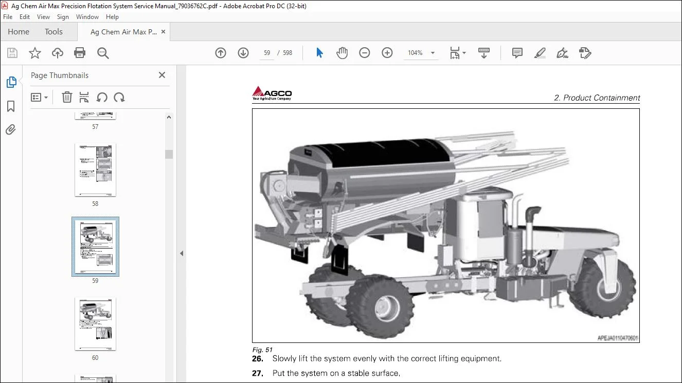
2 1 17 Removing the system 2-17
2 1 18 Installing the system 2-21
2 2 Granular bin 2-26
2 2 1 Removing the granular bin 2-26
2 2 2 Installing the granular bin 2-30
2 2 3 Removing the granular bin ladder 2-35
2 2 4 Installing the granular bin ladder 2-35
2 3 Spray-Max 2-37
2 3 1 Removing the Spray-Max liquid tank 2-37
2 3 2 Installing the Spray-Max liquid tank 2-40
2 3 3 Removing the sight gauge weldment 2-43
2 3 4 Installing the sight gauge weldment 2-43
2 3 5 Removing the sight gauge 2-44
2 3 6 Installing the sight gauge 2-45
3 Primary Product Distribution 3-1
3 1 Conveyor 3-3
3 1 1 Removing a conveyor chain 3-3
3 1 2 Install a conveyor chain 3-4
3 1 3 Adjust the conveyor chain 3-5
3 1 4 Remove a front idler shaft for the conveyor chain 3-7
3 1 5 Install a front idler shaft for the conveyor chain 3-8
3 1 6 Removing a conveyor chain gear box 3-10
3 1 7 Installing a conveyor chain gear box 3-11
3 1 8 Removing a conveyor chain drive shaft 3-12
3 1 9 Installing a conveyor chain drive shaft 3-14
3 1 10 Removing a conveyor chain rear idler shaft 3-16
3 1 11 Installing a conveyor chain rear idler shaft 3-17
3 2 Granular bin 3-19
3 2 1 Removing an electric clutch 3-19
3 2 2 Installing an electric clutch 3-20
3 2 3 Removing a metering wheel drive shaft 3-22
3 2 4 Installing a metering wheel drive shaft 3-23
3 2 5 Metering wheels 3-24
3 2 6 Removing a metering wheel 3-24
3 2 7 Installing a metering wheel 3-25
3 2 8 Removing the granular bin electric motor 3-26
3 2 9 Installing the granular bin electric motor 3-27
3 3 Fan 3-29
3 3 1 Removing a fan precleaner 3-29
3 3 2 Installing a fan precleaner 3-30
3 3 3 Removing a fan guard 3-30
3 3 4 Installing a fan guard 3-31
3 3 5 Removing the fan 3-31
3 3 6 Installing the fan 3-33
3 3 7 Removing the air supply tube 3-35
3 3 8 Installing the air supply tube 3-36
3 4 System Certification 3-37
3 4 1 Materials and equipment required 3-37
3 4 2 Calibrating the spreader 3-37
3 4 3 Checking the conveyor gate opening 3-38
3 4 4 Aligning the boom tubes to the manifold 3-38
3 4 5 Aligning the boom tips to the inner boom 3-39
3 4 6 Adjusting the weight for each boom tube 3-39
Application System
79036762C
~ A AGCO
v Ag,kuhu,o(ompaoy Table of contents
3 4 7 Adjusting the weight for each outlet deflector 3-40
3 4 8 Adjusting the outlet deflector 3-41
3 4 9 Adjusting the outlet deflector trim tab 3-42
3 4 1 0 Performing a bag test 3-42
3 4 11 Testing the manifold air pressure 3-46
3 4 12 Unloading the bin after spreading 3-47
3 5 Spray-Max 3-49
3 5 1 Removing the pump assembly 3-49
3 5 2 Installing the pump assembly 3-50
3 5 3 Removing the flowmeter 3-52
3 5 4 Disassembling the flowmeter 3-52
3 5 5 Assembling the flowmeter 3-53
3 5 6 Installing the flowmeter 3-54
3 5 7 Removing a control valve 3-54
3 5 8 Installing a control valve 3-55
4 Secondary Product Distribution 4-1
4 1 Outlet deflectors 4-3
4 1 1 Removing a center outlet deflector 4-3
4 1 2 Installing a center outlet deflector 4-3
4 1 3 Removing a boom outlet deflector 4-3
4 1 4 Installing a boom outlet deflector 4-4
5 Booms 5-1
5 1 Boom strut 5-3
5 1 1 Removing a boom strut 5-3
5 1 2 Installing a boom strut 5-4
5 1 3 Removing a boom strut pivot weldment 5-6
5 1 4 Installing a boom strut pivot weldment 5-9
5 1 5 Adjusting the boom strut length 5-12
5 2 Inner boom 5-13
5 2 1 Removing a boom tip cradle 5-13
5 2 2 Removing an inner boom 5-13
5 2 3 Removing a boom pivot weldment 5-15
5 2 4 Installing a boom pivot weldment 5-15
5 2 5 Installing an inner boom 5-16
5 2 6 Installing a boom tip cradle 5-18
5 3 Boom tips 5-19
5 3 1 Installing a boom tip 5-19
5 3 2 Removing a boom tip 5-20
6 Foam Marker 6-1
6 1 Foam marker components 6-3
6 1 1 Foam marker 6-3
6 1 2 Removing the foam marker tank 6-3
6 1 3 Removing the foam marker tank carrier 6-4
6 1 4 Installing the foam marker tank carrier 6-4
6 1 5 Installing the foam marker tank 6-4
6 1 6 Removing the foam marker regulator 6-5
6 1 7 Installing the foam marker regulator 6-7
6 1 8 Removing the foam marker enable solenoid 6-8
6 1 9 Installing the foam marker enable solenoid 6-9
6 1 10 Removing the foam marker pressure gauge 6-10
6 1 11 Installing the foam marker pressure gauge 6-10
6 1 12 Removing the foam marker solenoid valve 6-11
6 1 13 Installing the foam marker solenoid valve 6-12
6 2 Troubleshooting the foam marker system 6-13
Application System
79036762C
Table of contents ~•AGCO
Your Agriculture Company
7 Hydraulic System 7-1
7 1 Hydraulic system introduction 7-3
7 2 Hydraulic schematics 7-4
7 2 1 Fan and conveyor hydraulic schematic 7-4
7 2 2 Boom motion hydraulic schematic 7-5
7 3 Variable displacement pump 7-6
7 3 1 Removing the variable displacement pump 7-6
7 3 2 Installing the variable displacement pump 7-7
7 4 Load sense inline filter 7-9
7 4 1 Removing the load sense inline filter 7-9
7 4 2 Installing the load sense inline filter 7-10
7 5 Gear pump 7-11
7 5 1 Removing the gear pump 7-11
7 5 2 Installing the gear pump 7-12
7 6 High pressure filter assembly 7-13
7 6 1 Removing the high pressure filter assembly 7-13
7 6 2 Installing the high pressure filter assembly 7-14
7 7 Conveyor drive block 7-15
7 7 1 Removing the conveyor drive block 7-15
7 7 2 Installing the conveyor drive block 7-16
7 7 3 Operating the conveyors manually 7-16
7 8 Conveyor pressure gauge 7-18
7 8 1 Removing the conveyor pressure gauge 7-18
7 8 2 Installing the conveyor pressure gauge 7-19
7 9 Conveyor motor bypass valve 7-20
7 9 1 Removing a conveyor motor bypass valve 7-20
7 9 2 Installing a conveyor motor bypass valve 7-21
7 10 Conveyor motor 7-22
7 10 1 Removing a conveyor motor 7-22
7 10 2 Disassemble the conveyor motor 7-23
7 10 3 Assemble the conveyor motor 7-27
7 10 4 Installing a conveyor motor 7-31
7 11 Oil cooler 7-32
7 11 1 Removing an oil cooler 7-32
7 11 2 Installing an oil cooler 7-33
7 12 Oil cooler check valve 7-35
7 12 1 Removing the oil cooler check valve 7-35
7 12 2 Installing the oil cooler check valve 7-36
7 13 Low pressure filter assembly 7-37
7 13 1 Removing the low pressure filter assembly 7-37
7 13 2 Installing the low pressure filter assembly 7-38
7 14 Hydraulic tank 7-39
7 14 1 Removing the hydraulic tank 7-39
7 14 2 Installing the hydraulic tank 7-40
7 15 Fan pressure gauge 7-42
7 15 1 Removing the fan pressure gauge 7-42
7 15 2 Installing the fan pressure gauge 7-43
7 16 Fan speed servo valve 7-44
7 16 1 Removing the fan speed servo valve 7-44
7 16 2 Installing the fan speed servo valve 7-45
7 16 3 Adjusting the fan speed servo valve 7-48
7 17 Fan motor 7-49
7 17 1 Removing the fan motor 7-49
7 17 2 Installing the fan motor 7-51
Application System
79036762C
~ A AGCO
Your Agriculture Company Table of contents
7 18 Spray-Max control valve 7-54
7 18 1 Removing the Spray-Max control valve 7-54
7 18 2 Installing the Spray-Max control valve 7-55
7 19 Spray-Max pump motor 7-56
7 19 1 Disassembling the pump assembly 7-56
7 19 2 Assembling the pump assembly 7-57
7 20 Boom motion block 7-60
7 20 1 Removing the boom motion block 7-60
7 20 2 Installing the boom motion block 7-62
7 20 3 Operating the booms manually 7-63
7 21 Sequence valve block 7-65
7 21 1 Removing the sequence valve block 7-65
7 21 2 Disassembling the sequence valve block 7-66
7 21 3 Assembling the sequence valve block 7-67
7 21 4 Installing the sequence valve block 7-67
7 22 AutoBoom® valve block 7-69
7 22 1 Removing the AutoBoom® valve block 7-69
7 22 2 Installing the AutoBoom® valve block 7-70
7 23 Boom latch cylinders 7-72
7 23 1 Removing a boom latch cylinder 7-72
7 23 2 Installing a boom latch cylinder 7-73
7 24 Boom swing cylinder 7-74
7 24 1 Removing a boom swing cylinder 7-74
7 24 2 Installing a boom swing cylinder 7-75
7 25 Boom swing cylinder accumulator 7-77
7 25 1 Removing a boom swing cylinder accumulator 7-77
7 25 2 Installing a boom swing cylinder accumulator 7-78
7 26 Boom suspension cylinder 7-79
7 26 1 Removing a boom suspension cylinder 7-79
7 26 2 Installing a boom suspension cylinder 7-80
7 27 Boom suspension cylinder accumulator 7-82
7 27 1 Removing a boom suspension cylinder accumulator 7-82
7 27 2 Installing a boom suspension cylinder accumulator 7-83
7 28 Hydraulic system testing and adjusting 7-84
7 28 1 Adjusting the fan speed servo valve 7-84
7 28 2 Operating the booms manually 7-84
7 28 3 Operating the conveyors manually 7-85
7 28 4 Troubleshooting the hydraulic gear pump 7-86
7 28 5 Troubleshooting the variable displacement pump 7-87
7 28 6 Troubleshooting the conveyor drive block 7-87
7 28 7 Troubleshooting the conveyor motor bypass valve 7-88
7 28 8 Troubleshooting the conveyor motor 7-88
7 28 9 Troubleshooting the fan speed servo valve 7-89
7 29 Hydraulic system maintenance 7-91
7 29 1 Checking the hydraulic oil 7-91
7 29 2 Changing the hydraulic oil 7-91
7 29 3 Bleeding the hydraulic system 7-92
8 Electrical System 8-1
8 1 Application rate sensor 8-5
8 1 1 Removing an application rate sensor 8-5
8 1 2 Installing an application rate sensor 8-6
8 2 Fan speed sensor 8-8
8 2 1 Removing the fan speed sensor 8-8
8 2 2 Installing the fan speed sensor 8-8
Application System
79036762C
Table of contents ~•AGCO
Your Agriculture Company
8 3 Bin full empty sensor 8-9
8 3 1 Removing a bin full empty sensor 8-9
8 3 2 Installing a bin full empty sensor 8-1 0
8 4 Fault codes 8-11
8 4 1 Code R610 8-11
8 4 1 1 Boom fold schematic 8-12
8 4 2 Code R611 8-15
8 4 2 1 Boom fold schematic 8-17
8 4 3 Code R612 8-20
8 4 3 1 Boom fold schematic 8-22
8 4 4 Code R613 8-25
8 4 4 1 Boom fold schematic 8-27
8 4 5 Code R614 8-30
8 4 5 1 Boom fold schematic 8-32
8 4 6 Code R615 8-35
8 4 6 1 Boom fold schematic 8-37
8 4 7 Code R616 8-40
8 4 7 1 Boom fold schematic 8-42
8 4 8 Code R617 8-45
8 4 8 1 Boom fold schematic 8-47
8 4 9 Code R618 8-50
8 4 9 1 Boom motion system schematic 8-52
8 4 10 Code R619 8-53
8 4 10 1 Boom motion system schematic 8-55
8 4 11 Code R620 8-56
8 4 11 1 Boom motion system schematic 8-58
8 4 12 Code R621 8-59
8 4 12 1 Boom motion system schematic 8-61
8 4 13 Code R622 8-62
8 4 13 1 Boom motion system schematic 8-64
8 4 14 Code R623 8-65
8 4 14 1 Boom motion system schematic 8-67
8 4 15 Code R624 8-68
8 4 1 5 1 Boom motion system schematic 8-70
8 4 16 Code R625 8-71
8 4 16 1 Boom motion system schematic 8-73
8 4 17 Code R626 8-74
8 4 17 1 Boom motion system schematic 8-76
8 4 18 Code R627 8-77
8 4 18 1 Boom motion system schematic 8-79
8 4 19 Code R628 8-80
8 4 19 1 Foam marker system schematic 8-82
8 4 20 Code R629 8-83
8 4 20 1 Foam marker system schematic 8-85
8 4 21 Code R630 8-86
8 4 21 1 Foam marker system schematic 8-88
8 4 22 Code R631 8-89
8 4 22 1 Foam marker system schematic 8-91
8 4 23 Code R632 8-92
8 4 23 1 Foam marker system schematic 8-94
8 4 24 Code R633 8-95
8 4 24 1 Foam marker system schematic 8-97
8 4 25 Code R634 8-98
8 4 25 1 Tarp electrical schematic 8-100
8 4 26 Code R635 8-101
8 4 26 1 Tarp electrical schematic 8-103
8 4 27 Code R636 8-104
8 4 27 1 Tarp electrical schematic 8-106
Application System
79036762C
~ A AGCO
Your Agriculture Company Table of contents
8 4 28 Code R637 8-107
8 4 28 1 Tarp electrical schematic 8-109
8 4 29 Code R638 8-110
8 4 29 1 Boom apply schematic 8-112
8 4 30 Code R639 8-113
8 4 30 1 Boom apply schematic 8-115
8 4 31 Code R640 8-116
8 4 31 1 Boom apply schematic 8-118
8 4 32 Code R641 8-119
8 4 32 1 Boom apply schematic 8-121
8 4 33 Code R642 8-122
8 4 33 1 Boom apply schematic 8-124
8 4 34 Code R643 8-125
8 4 34 1 Boom apply schematic 8-127
8 4 35 Code R644 8-128
8 4 35 1 Fan control schematic 8-129
8 4 36 Code R645 8-130
8 4 36 1 Fan control schematic 8-131
8 4 39 Code R848 8-137
8 4 39 1 System hazard warning lamps electrical circuits 8-139
8 4 40 Code R849 8-140
8 4 40 1 System hazard warning lamps electrical circuits 8-142
8 4 41 Code R850 8-143
8 4 41 1 System hazard warning lamps electrical circuits 8-145
8 4 42 Code R851 8-146
8 4 42 1 System hazard warning lamps electrical circuits 8-148
8 4 43 Code R852 8-149
8 4 43 1 System hazard warning lamps electrical circuits 8-150
8 4 44 Code R853 8-151
8 4 44 1 System hazard warning lamps electrical circuits 8-152
8 4 45 Code R854 8-153
8 4 45 1 System hazard warning lamps electrical circuits 8-154
8 4 46 Code R855 8-155
8 4 46 1 System hazard warning lamps electrical circuits 8-157
8 4 47 Code R856 8-158
8 4 47 1 System hazard warning lamps electrical circuits 8-159
8 4 48 Code R857 8-160
8 4 48 1 System hazard warning lamps electrical circuits 8-161
8 4 49 Code R858 8-162
8 4 49 1 System hazard warning lamps electrical circuits 8-163
8 4 50 Code R859 8-164
8 4 50 1 System hazard warning lamps electrical circuits 8-166
9 Pressure Washer and Rinse System 9-1
9 1 Pressure washer and rinse system components 9-3
9 1 1 Removing the pressure washer/rinse tank 9-3
9 1 2 Installing the pressure washer/rinse tank 9-3
9 1 3 Removing the pressure washer/rinse tank carrier 9-4
9 1 4 Installing the pressure washer/rinse tank carrier 9-5
10 Diagrams 10-1
10 1 Electrical schematics 10-3
10 1 1 AirMax Precision electrical schematics 10-3
11 Index lndex-1
Customer Support: [email protected]
PLEASE NOTE:
- This is the SAME exact manual used by your dealers to fix your vehicle.
- The same can be yours in the next 2-3 mins as you will be directed to the download page immediately after paying for the manual.
- Any queries / doubts regarding your purchase, please feel free to contact [email protected]
S.V