Ag Chem 6103 8103 8104 8144 TerraGator Can Bus Service Manual_AG133547B – PDF DOWNLOAD
Original price was: $86.95.$28.95Current price is: $28.95.
Ag Chem 6103 8103 8104 8144 TerraGator Can Bus Service Manual_AG133547B – PDF DOWNLOAD
Description
Ag Chem 6103 8103 8104 8144 TerraGator Can Bus Service Manual_AG133547B – PDF DOWNLOAD
FILE DETAILS:
Ag Chem 6103 8103 8104 8144 TerraGator Can Bus Service Manual_AG133547B – PDF DOWNLOAD
Language : English
Pages : 314
Downloadable : Yes
File Type : PDF
Size: 37.2 MB
IMAGES PREVIEW OF THE MANUAL:
DESCRIPTION:
Ag Chem 6103 8103 8104 8144 TerraGator Can Bus Service Manual_AG133547B – PDF DOWNLOAD
GENERAL:
- This manual is not intended to replace the operators manual, parts manual or other available print manuals. Refer to the chassis and system manual for more operating, maintenance and safety information.
- Information, illustrations and specifications in this manual are based on the latest information available at the time of publication. All rights are reserved to make changes at any time without notice.
FOLLOW SAFETY INSTRUCTIONS:
Learn how to operate the machine and how to use all controls properly BEFORE OPERATION. Do not let anyone operate the machine or system, or perform service and maintenance procedures without proper instruction.
- Carefully read, learn and understand all safety messages and information in this manual, the operator’s manual and the machine’s safety signs. Keep safety signs in good condition.
- Replace missing or damaged safety signs Replacement safety signs are available from AGCO Corporation. Make sure new equipment components and repair parts include the current safety signs.
- Replace safety treads when worn, damaged or missing. Replace hand rails and steps if they become damaged. Keep the machine, all components and systems in the proper working condition. Unauthorized modifications to the machine may impair the function and/or safety, affect machine life, and void the warranty.
Protect Yourself:
Wear all the protective clothing and personal safety devices issued to you or called by the job conditions.
For example, you may need:
• A hard hat
• Safety glasses, goggles, or face shield
• Hearing protection
• Respirator or filter mask
• Inclement weather clothing
• Reflective clothing
• Heavy gloves (neoprene for chemicals)
• Safety shoes: (leather for rough work)
• Other items appropriate to the task
DO NOT wear loose clothing, jewelry or other items and tie up long hair which could catch on controls or other parts of the equipment.
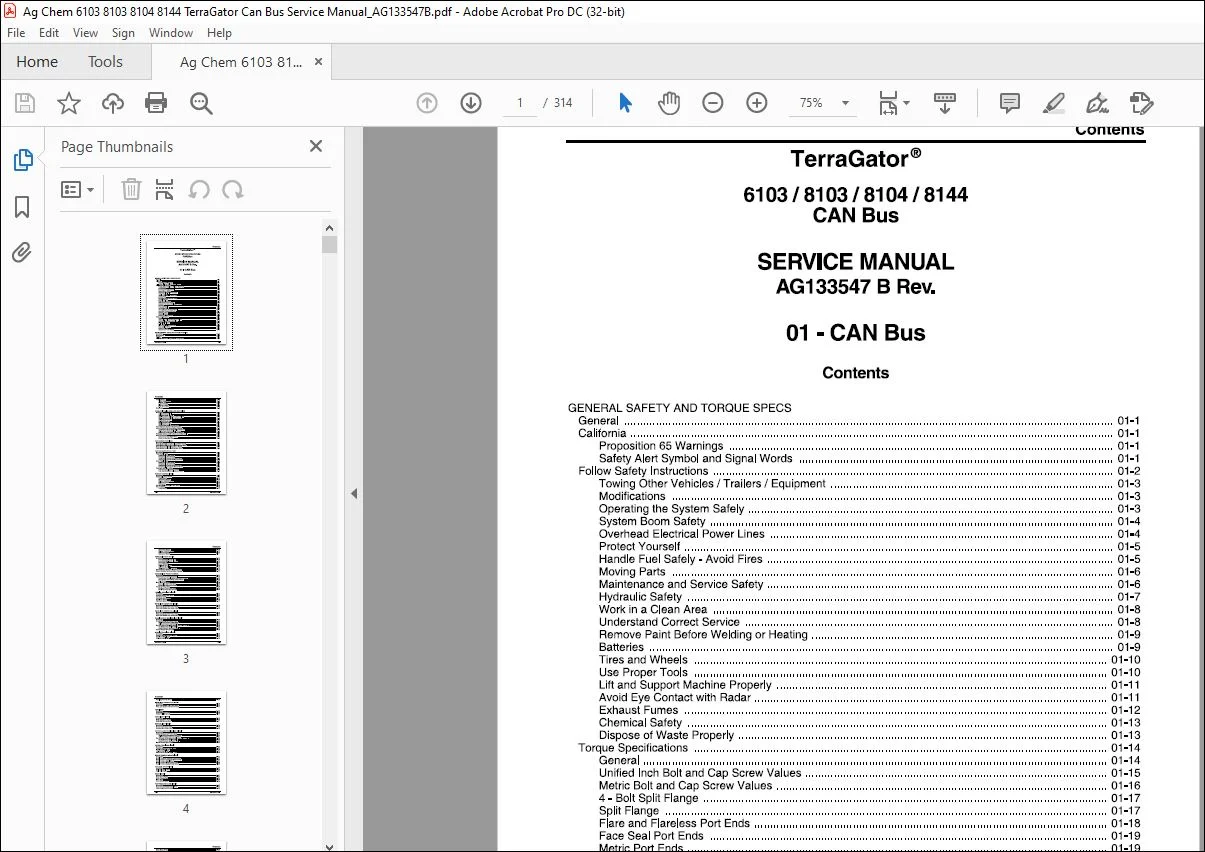
TABLE OF CONTENTS:
Ag Chem 6103 8103 8104 8144 TerraGator Can Bus Service Manual_AG133547B – PDF DOWNLOAD
GENERAL SAFETY AND TORQUE SPECS
Contents
General 01-1
California 01-1
Proposition 65 Warnings 01-1
Safety Alert Symbol and Signal Words 01-1
Follow Safety Instructions 01-2
Towing Other Vehicles/ Trailers/ Equipment 01-3
Modifications 01-3
Operating the System Safely 01-3
System Boom Safety 01-4
Overhead Electrical Power Lines 01-4
Protect Yourself 01-5
Handle Fuel Safely – Avoid Fires 01-5
Moving Parts 01-6
Maintenance and Service Safety 01-6
Hydraulic Safety 01-7
Work in a Clean Area 01-8
Understand Correct Service 01-8
Remove Paint Before Welding or Heating 01-9
Batteries 01-9
Tires and Wheels 01-10
Use Proper Tools 01-10
Lift and Support Machine Properly 01-11
Avoid Eye Contact with Radar 01-11
Exhaust Fumes 01-12
Chemical Safety 01-13
Dispose of Waste Properly 01-13
Torque Specifications 01-14
General 01-14
Unified Inch Bolt and Cap Screw Values 01-15
Metric Bolt and Cap Screw Values 01-16
4 – Bolt Split Flange 01-17
Split Flange 01-17
Flare and Flareless Port Ends 01-18
Face Seal Port Ends 01-19
Metric Port Ends 01-19
Adapters and Tube Fittings 01-20
CAN BUS MANUAL USAGE AND SYSTEM OVERVIEW
Description 01-23
Requirements 01-23
Definition 01-24
Following are the Primary CAN Bus Components 01-25
AG133547 B Rev 01-i
Contents
Troubleshooting 01-45
1 Over Temp/Current 01-45
2 Open Load 01-45
3 Short To GND 01-45
4 Short to BaVOT 01-46
5 No Error Listed 01-46
Error Codes 01-46
BOOM MOTION MAIN ENABLE AND HEAD RINSE
Description 01-59
Left-Hand Boom Fold In 01-59
Left-Hand Boom Fold Out 01-59
Right-Hand Boom Fold Out or Boom Unlatch 01-60
Right-Hand Boom Fold In or Boom Latch 01-60
Left-Hand Boom Down 01-60
Lett-Hand Boom Up 01-61
Right-Hand Boom Down 01-61
Right-Hand Boom Up 01-61
Boom Motion Enable or Head Rinse 01-61
Power Circuit for the Boom Motion Function 01-62
Ground Circuit for the Boom Motion Functions 01-64
Liquid System Boom Motion Solenoid Ground 01-64
Air-Max Boom Motion Solenoid Ground 01-65
AirSpreader Boom Motion Solenoid Ground 01-66
Power and Ground Circuit for the Boom Motion Enable 01-67
Head Rinse Circuit 01-67
Power for the Head Rinse Circuit 01-67
Ground for the Head Rinse 01-70
FOAM MARKER FUNCTIONS
Description 01-71
Foam Marker Right and Left Solenoid Power Circuit 01-72
Foam Marker Right and Left Solenoid Ground Circuit 01-74
Foam Marker Enable Solenoid Power Circuit 01-75
Foam Marker Enable Solenoid Ground Circuit 01-76
PUMP AND SUMP OR ROLL TARP
Description 01-77
Pump Enable Circuit 01-77
Pump Enable Power Circuit 01-77
Pump Enable Ground Circuit 01-81
Pump Enable Remote Box Power Circuit 01-83
Pump Enable Remote Box Ground Circuit 01-85
Sump Enable Circuit 01-86
Sump Enable Power Circuit 01-86
Sump Enable Ground Circuit 01-89
Sump Enable Remote Box Power Circuit 01-91
Sump Enable Remote Box Ground Circuit 01-93
Tarp Open and Close Circuit 01-94
Tarp Open and Close Power Circuit 01-94
Tarp Magnetic Switch Relay Ground Circuit 01-96
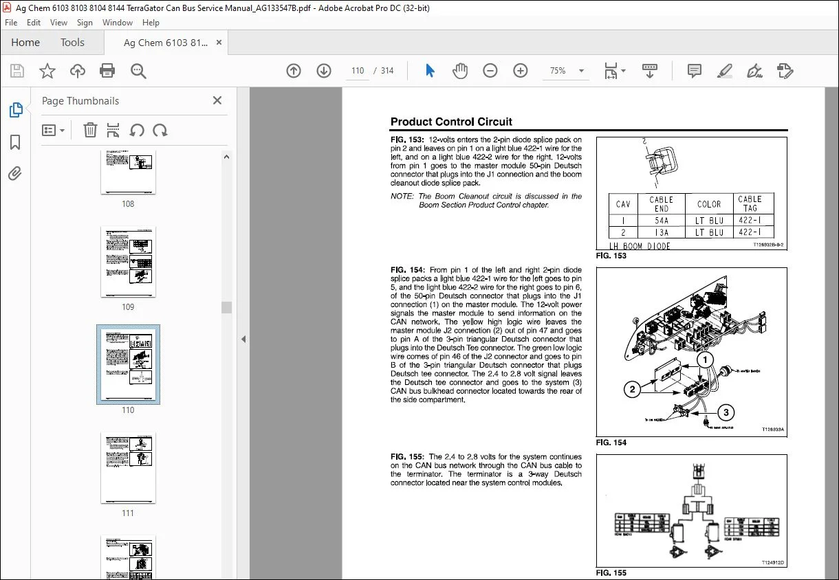
PRODUCT CONTROL CIRCUIT
Description 01-97
Master Apply Power Circuit 01-98
Liquid System 01-100
Air Spreader System 01-100
Air-Max 1000/2000 System 01-102
Air-Max V System 01-102
New Leader 01-102
Left and Right-Hand Apply Power Circuit 01-103
Ground Circuits 01-106
Liquid System 01-107
01-ii AG133547 B Rev
Contents
Air Spreader System 01-108
Air-Max 1000/2000 System 01-109
Air-Max V System 01-110
New Leader System 01-111
BOOM MOTION MAST AND TIP
Description 01-113
Boom Mast Right-Hand Tilt Up 01-113
Boom Mast Right-Hand Tilt Down 01-113
Boom Hoist Up 01-114
Boom Hoist Down 01-114
Left-Hand Tip Fold Out 01-114
Left-Hand Tip Fold In 01-115
Right-Hand Tip Fold In and Out 01-115
Power Circuit for the Boom Motion Functions 01-116
Ground Circuit for the Boom Motion Functions 01-119
BOOM SECTION PRODUCT CONTROL
Description 01-121
Liquid System Boom Product Control 01-122
Boom Section Control (Quick Stop) Power Circuits 01-122
Boom Section (Quick Stop) Ground Circuits 01-126
Boom Sense 01-127
Boom Clean Out Circuit 01-128
Boom Clean Out Power Circuit 01-128
Boom Clean Out Ground Circuit 01-131
Wet Boom Pump Circuit 01-133
Wet Boom Pump Power Circuit 01-133
Wet Boom Pump Ground Circuit 01-136
LOW-HIGH BEAM LIGHT CIRCUIT
Description 01-139
Low/High Beam Power Circuit 01-139
Low Beam Circuit 01-141
Low Beam Ground Circuit 01-143
High Beam Circuit 01-144
High Beam Ground Circuit 01-147
WORK LIGHT NUMBER ONE CIRCUIT
Description 01-149
Work Light Number One Power Circuit 01-149
Work Light Number One Ground Circuit 01-152
WORK LIGHT NUMBER TWO CIRCUIT
Description 01-153
Work Light Number Two Power Circuit 01-153
Work Light Number Two Ground Circuit 01-157
CHASSIS HAZARD WARNING LIGHT CIRCUIT
Description 01-159
Chassis Warning Light Power Circuit 01-159
Right-Hand Chassis Hazard Circuit 01-161
Left-Hand Chassis Hazard Circuit 01-163
Key Off Power for the Master Module and the 1/0 Module 01-165
Key Off Power for the 1/0 Module 01-166
Key Off Power for the Master Module 01-167
Chassis Hazard Ground Circuit 01-168
CHASSIS TURN SIGNAL CIRCUIT
Description 01-169
Power for the Chassis Signal Lights 01-169
Right-Hand Signal Light 01-170
Left-Hand Signal Light 01-173
AG133547 B Rev 01-iii
Contents
Signal Light Ground Circuit 01-176
WORK LIGHT NUMBER FOUR CIRCUIT
Description 01-177
Work Light Number Four Power Circuit 01-177
Work Light Number Four Ground Circuit 01-181
PARK LIGHTS
Description 01-183
Park Light Power Circuit 01-183
System Taillight Ground 01-187
BRAKE LIGHTS CIRCUIT
Description 01-189
Brake Light Power Circuit 01-189
Brake Light Ground Circuit 01-191
REVERSE LIGHT CIRCUIT
Description 01-193
Reverse Light Power Circuit 01-193
Reverse Light Ground Circuit 01-196
SYSTEM HAZARD WARNING LIGHT CIRCUIT
Description 01-197
System Warning Light Power Circuit 01-197
Right-Hand System Hazard Light Circuit 01-199
Left-Hand System Hazard Light Circuit 01-201
Key Off Power for the Master Module and the 1/0 Module 01-203
Key Off Power for the 1/0 Module 01-204
Key Off Power for the Master Module 01-206
System Hazard Light Ground 01-207
SYSTEM TURN SIGNAL CIRCUIT
Description 01-209
Power for the System Signal Lights 01-209
Right-Hand Signal Light 01-210
Left-Hand Signal Light 01-213
Ground for the System Signal Lights 01-216
NOZZLE PRESSURE GAUGE CIRCUIT
Description 01-217
Nozzle Pressure Transducer Power Circuit 01-217
Nozzle Pressure Transducer Ground Circuit 01-219
Nozzle Pressure Signal Circuit 01-221
Nozzle Pressure Gauge Power Circuit 01-223
Nozzle Pressure Gauge Ground Circuit 01-225
FUEL LEVEL GAUGE CIRCUIT
Description 01-227
Fuel Level Signal Circuit 01-228
Fuel Level Ground 01-230
RADAR CIRCUIT
Description 01-231
Radar Power Circuit 01-231
Radar Present Signal 01-233
Radar Signal 01-234
Radar Ground Circuit 01-235
PUMP PRESSURE GAUGE CIRCUIT
Description 01-237
Pump Pressure Gauge Signal Circuit 01-237
Pump Sender Ground Circuit 01-240
01-iv AG133547 B Rev
Contents
Pump Gauge Power 01-242
Pump Pressure Gauge Ground Circuit 01-244
TRANSMISSION CONVERTER OPEN LIGHT
Description 01-247
Transmission Converter Open Light Power Circuit 01-247
Transmission Converter Open Light Ground Circuit 01-248
AIR PRESSURE GAUGE
Description 01-249
Air Pressure Signal Circuit 01-249
PUMP SUMP ON CIRCUIT
Description 01-251
Power for the Pump and Switch Lights 01-251
Ground for the Pump Switch Light 01-253
Ground for the Sump Switch Light 01-254
FOAM MARKER ON
Description 01-255
Power for the Foam Marker Switch Light 01-255
Ground for the Foam Marker Switch Light 01-256
BEACON CIRCUIT
Description 01-257
Beacon Power Circuit 01-257
Beacon Ground Circuit 01-260
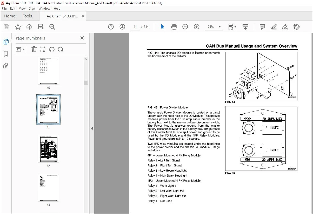
1/0 MODULES AND POWER DIVIDERS
Description 01-261
1/0 Module Power and Ground Circuits 01-261
Front Chassis 1/0 Interface Module Power Supply 01-261
Front Chassis 1/0 Module Ground 01-263
System 1/0 Module Power Supply 01-264
System 1/0 Ground Circuit 01-266
Power Divider Power and Ground Circuits 01-268
Chassis Power Divider Power and Ground 01-268
System Power Divider Power and Ground 01-269
HVAC-CAB PRESSURIZATION BLOWER CIRCUIT
Description 01-271
Pressure Blower Power Circuit 01-271
HVAC Blower Motor Ground Circuit 01-272
HVAC Power Circuit 01-273
Overhead HVAC Power 01-274
Under the Seat HVAC Power 01-274
Fan Switch Three Speed Circuit 01-275
A/C Switch Circuit 01-277
Heater Switch Circuit 01-279
HVAC Ground Circuit 01-280
RADIO CIRCUIT
Description 01-281
Radio Switched Power Circuit 01-281
Radio Unswitched Memory Power 01-282
Radio Ground Circuit 01-283
Speaker Wires 01-284
Front Speaker Wires 01-284
Rear Speaker Wires 01-285
SEAT CIRCUIT
Description 01-287
Seat Power Circuit 01-287
AG133547 B Rev 01-v
Contents
Seat Ground Circuit 01-288
WINDSHIELD WASHER CIRCUIT
Description 01-289
Windshield Washer Power Circuit 01-289
Windshield Washer Ground Circuit 01-291
WINDSHIELD WIPER CIRCUIT
Description 01-293
Wiper in the Off/Park Position 01-294
Wiper in the Low Speed Position 01-295
Wiper in the High Speed Position 01-296
Wiper Ground Circuit 01-297
WORK LIGHT NUMBER THREE CIRCUIT
Description 01-299
Work Light Number Three Power Circuit 01-299
Right-Hand Circuit 01-301
Left-Hand Circuit 01-302
Work Light #3 Ground Circuit 01-303
Right-Hand Circuit 01-303
Left-Hand Circuit 01-304
INDEX 01-305
Customer Support: [email protected]
PLEASE NOTE:
- This is not a physical manual but a digital manual – meaning no physical copy will be couriered to you. The manual can be yours in the next 2 mins as once you make the payment, you will be directed to the download page IMMEDIATELY.
- This is the same manual used by the dealers inorder to diagnose your vehicle of its faults.
- Require some other service manual or have any queries: please WRITE to us at [email protected]
S.V