

2009 Arctic Cat 400trv 500 550 700 Atv Service Manual
FILE DETAILS:
LANGUAGE:ENGLISH
PAGES:349
DOWNLOADABLE:YES
FILE TYPE:PDF
VIDEO PREVIEW OF THE MANUAL:

DESCRIPTION:
2009 Arctic Cat 400trv 500 550 700 Atv Service Manual
FOREWORD:
This Arctic Cat Service Manual contains service, maintenance, and troubleshooting information for certain 2009 Arctic Cat ATV models (see cover). The complete manual is designed to aid service personnel in service-oriented applications.
Arctic Cat offers additional publications (when they become available) to aid in servicing other ATV models. To service models not included in this manual, please refer to the following publications:
• 2009 Y-12 Service Manual
• 2009 T-14 Service Manual
• 2009 DVX 300/250 Utility Service Manual
• 2009 366 Service Manual
• 2009 700 Mud Pro Service Manual Supplement
This manual is divided into sections. Each section covers a specific ATV component or system and, in addition to the standard service procedures, includes disassembling, inspecting, and assembling instructions. When using this manual as a guide, the technician should use discretion as to how much disassembly is needed to correct any given condition.
- The service technician should become familiar with the operation and construction of each component or system by carefully studying the complete manual. This manual will assist the service technician in becoming more aware of and efficient with servicing procedures. Such efficiency not only helps build consumer confidence but also saves time and labor.
- All Arctic Cat ATV publications and decals display the words Warning, Caution, Note, and At This Point to emphasize important information. The symbol ! WARNING identifies personal safety-related information. Be sure to follow the directive because it deals with the possibility of severe personal injury or even death. The symbol ! CAUTION identifies unsafe practices which may result in ATV-related damage. Follow the directive because it deals with the possibility of damaging part or parts of the ATV. The symbol ? NOTE: identifies supplementary information worthy of particular attention. The symbol ? AT THIS POINT directs the technician to certain and specific procedures to promote efficiency and to improve clarity.
- At the time of publication, all information, photographs, and illustrations were technically correct. Some photographs used in this manual are used for clarity purposes only and are not designed to depict actual conditions. Because Arctic Cat Inc. constantly refines and improves its products, no retroactive obligation is incurred.
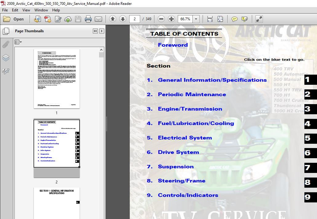
TABLE OF CONTENTS:
2009 Arctic Cat 400trv 500 550 700 Atv Service Manual
General Specifications 1-2
Torque Specifications 1-3
Torque Conversions (ft-lb/N-m) 1-6
Tightening Torque (General Bolts) 1-6
Break-In Procedure 1-6
Gasoline – Oil – Lubricant 1-6
Genuine Parts 1-7
Preparation For Storage 1-7
Preparation After Storage 1-8
Periodic Maintenance Chart 2-2
Periodic Maintenance 2-3
Lubrication Points 2-3
Air Filter 2-3
Valve/Tappet Clearance
(Feeler Gauge Procedure) 2-4
Valve/Tappet Clearance
(Valve Adjuster Procedure)
(400/500/H1 Models) 2-5
Valve/Tappet Clearance
(Valve Adjuster Procedure) (H2 Models) 2-6
Testing Engine Compression 2-6
Spark Plug(s) 2-7
Muffler/Spark Arrester 2-7
Engine/Transmission Oil – Filter – Strainer 2-8
Front Differential/Rear Drive Lubricant 2-10
Adjusting Clutch (500 Manual Transmission) 2-11
Steering Components 2-11
Driveshaft/Coupling 2-11
Suspension/Shock Absorbers/Bushings 2-11
Nuts/Bolts/Cap Screws 2-12
Headlights/Taillight-Brakelight 2-12
Shift Lever 2-13
Frame/Welds/Racks 2-14
Electrical Connections 2-14
Hydraulic Brake Systems 2-14
Burnishing Brake Pads 2-15
Checking/Replacing V-Belt
(Automatic Transmission) 2-16
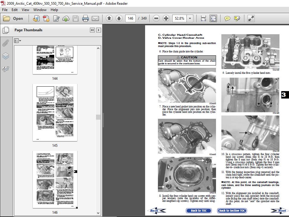
Engine/Transmission 3-2
Specifications (400) 3-2
Specifications (500) 3-3
Specifications (H1 Models) 3-4
Specifications (H2 Models) 3-4
Troubleshooting 3-5
400 Table of Contents 3-9
500 (Automatic Transmission)/H1 Models
Table of Contents 3-50
500 (Manual Transmission) Table of Contents 3-102
H2 Models Table of Contents 3-166
Fuel/Lubrication/Cooling 4-2
Carburetor Specifications (400/500) 4-2
Carburetor Schematics (400/500) 4-2
Carburetor (400/500) 4-2
Electric Choke (400/500) 4-7
Electronic Fuel Injection (EFI Models) 4-8
Throttle Cable Free-Play 4-10
Engine RPM (Idle) 4-11
Gas Tank 4-11
Oil Filter/Oil Pump 4-12
Testing Oil Pump Pressure 4-12
Oil Cooler (400/700/H2 Models) 4-12
Liquid Cooling System (500/H1/H2 Models) 4-13
Electric Fuel Pump/Fuel Level Sensor
(EFI Models) 4-18
Vacuum Pulse Fuel Pump (500) 4-20
Troubleshooting (400/500) 4-21
Troubleshooting (EFI Models) 4-21
Electrical System 5-2
Specifications 5-2
Battery 5-3
RPM Limiter 5-4
Testing Electrical Components 5-4
Accessory Receptacle/Connector 5-4
Brakelight Switch (Auxiliary) 5-4
Brakelight Switch (Handlebar Control) 5-5
Oil Temperature and Cooling Fan Switches (400) 5-5
Coolant Temperature and Cooling Fan Switches
(500) 5-6
Engine Coolant Temperature (ECT) Sensor
(EFI Models) 5-6
Fan Motor 5-7
Power Distribution Module (PDM) 5-7
Ignition Coil 5-8
EFI Sensors/Components (EFI Models) 5-10
Speed Sensor 5-11
Ignition Switch 5-11
Handlebar Control Switches 5-12
Front Drive Selector Switch 5-13
Front Drive Selector Actuator (400/500) 5-14
Front Drive/Differential Lock Actuator
(H1/H2 Models) 5-14
Differential Lock Switch (500) 5-15
Differential Lock Control Switch
(H1/H2 Models) 5-15
Stator Coil (400/500) 5-15
Stator Coil/Crankshaft Position (CKP) Sensor
(EFI Models) 5-16
Starter Relay 5-17
Starter Motor 5-18
CDI Unit (400/500) 5-22
Electronic Control Unit (ECU) (EFI Models) 5-22
Regulator/Rectifier 5-22
Headlights 5-22
Taillight – Brakelight 5-23
Ignition Timing 5-23
ECU Error Codes (EFI Models) 5-23
Tilt Sensor (EFI Models) 5-24
Throttle Position Sensor (TPS) (EFI Models) 5-25
Troubleshooting 5-28
Drive System 6-2
Front Drive Actuator (400/500)/Electronic
Differential Lock (H1/H2 Models) 6-2
Front Differential 6-3
Drive Axles 6-17
Rear Gear Case 6-21
Hub 6-23
Hydraulic Brake Caliper 6-25
Troubleshooting Drive System 6-26
Troubleshooting Brake System 6-27
Suspension 7-2
Shock Absorbers 7-2
Front A-Arms 7-3
Rear A-Arms 7-5
Wheels and Tires 7-7
Troubleshooting 7-8
Steering/Frame 8-2
Steering Post/Tie Rods 8-2
Handlebar Grip 8-5
Steering Knuckles 8-6
Measuring/Adjusting Toe-In 8-8
Front Rack 8-9
Front Bumper Assembly 8-9
Front Body Panel/Side Panels 8-10
Footrests 8-13
Belly Panel 8-14
Exhaust System 8-14
Rear Body Panel/Rack 8-14
Taillight Assembly 8-15
Seat 8-16
Troubleshooting 8-17
Hand Brake Lever/Master Cylinder Assembly 9-2
Throttle Control 9-3
Front Differential Lock Cable (500) 9-4
Shift Lever 9-4
Speedometer/Tachometer/LCD 9-5
IMAGES PREVIEW OF THE MANUAL:

PLEASE NOTE:
- This is the SAME exact manual used by your dealers to fix your vehicle.
- The same can be yours in the next 2-3 mins as you will be directed to the download page immediately after paying for the manual.
- Any queries / doubts regarding your purchase, please feel free to contact [email protected]


