

2007 Evinrude 40 50 60 HP Service Manual
FILE DETAILS:
2007 Evinrude 40 50 60 HP Service Manual
Language: English
Size: 27.5 MB
Pages: 358
Format: PDF
Downloadable: YES
DESCRIPTION:
2007 Evinrude 40 50 60 HP Service Manual
INFORMATION:
Maintenance, replacement, or repair of the emission control devices and systems may be performed by any marine SI (spark ignition) engine repair establishment or individual. Manufacturer’s Responsibility Beginning with 1999 model year outboards, manufacturers of marine outboards must determine the exhaust emission levels for each outboard horsepower family and certify these outboards with the United States of America Environmental Protection Agency (EPA). An emissions control information label, showing emission levels and outboard specifications, must be placed on each outboard at the time of manufacture.
Dealer’s Responsibility :
When performing service on all 1999 and more recent Evinrude/Johnson outboards that carry an emissions control information label, adjustments must be kept within published factory specifications. Replacement or repair of any emission related component must be executed in a manner that maintains emission levels within the prescribed certification standards. Dealers are not to modify the outboard in any manner that would alter the horsepower or allow emission levels to exceed their predetermined factory specifications. Exceptions include manufacturer’s prescribed changes, such as altitude adjustments, for example.
Owner’s Responsibility: The owner/operator is required to have outboard maintenance performed to maintain emission levels within prescribed certification standards.
TABLE OF CONTENTS:
2007 Evinrude 40 50 60 HP Service Manual
<— Return to Menu 0
INTRODUCTION 7
MODELS COVERED IN THIS MANUAL 8
Identifying Model and Serial Numbers 8
MODEL DESIGNATION 9
TYPICAL PAGE – A 10
TYPICAL PAGE – B 11
TYPICAL PAGE – C 12
TYPICAL PAGE – D 13
ABBREVIATIONS USED IN THIS MANUAL 14
Units of Measurement 14
List of Abbreviations 14
ENGINE EMISSIONS INFORMATION 15
Manufacturer’s Responsibility 15
Dealer’s Responsibility 15
Owner’s Responsibility 15
EPA Emission Regulations 15
PRODUCT REFERENCE AND ILLUSTRATIONS 16
SYMBOLS 16
Electrical 16
Values 17
NOTES 18
Technician’s Notes 18
Related Documents 18
SERVICE SPECIFICATIONS AND SPECIAL TOOLS 19
TECHNICAL DATA 20
STANDARD TORQUE SPECIFICATIONS 22
SPECIAL TOOLS 23
Electrical / Ignition 23
Fuel System 24
Gearcase 25
Powerhead 26
Starter 27
Universal 28
SHOP AIDS 30
INSTALLATION AND PREDELIVERY 33
BOAT RIGGING 34
Remote Controls 34
Battery Installation 36
Battery Switches and Multiple Batteries 37
Battery and Switch Wiring Diagrams 39
Fuel System Requirements 41
Cable and Hose Installation 43
OUTBOARD INSTALLATION 48
Hull Preparation 48
Transom Measuring and Drilling 49
Drilling and Hardware Diagrams 52
Lifting the Outboard 54
Steering Systems 54
Outboard Mounting 56
OUTBOARD RIGGING 58
Cable, Hose, and Wire Routing 58
Control Cable Adjustments 58
Electrical Harness Connections 60
Water Pressure Gauge 60
FUEL AND OIL PRIMING 61
Fuel Requirements 61
Fuel System Priming 62
Oil Requirements 63
Oil Injection Rate 63
SystemCheck Low Oil Warning Test 63
Oil Supply Priming 64
Break-In Oiling 64
BEFORE START-UP 65
Gearcase Lubricant 65
Oil Level 65
Trim and Tilt Fluid 65
RUNNING CHECKS 66
SystemCheck Operation 66
Fuel System 66
Emergency Stop / Key Switch 66
Remote Control Operation 66
Start-In-Gear Prevention 66
Tachometer Pulse Setting 67
Water Pump Overboard Indicator 67
Operating Temperature 67
Idle Speed 67
Break-In 67
PROPELLERS 68
Propeller Selection 68
Propeller Hardware Installation 69
FINAL ADJUSTMENTS 70
Trim Sending Unit Adjustment 70
Trim Tab Adjustment 71
Dual-Outboard Alignment 72
MAINTENANCE 73
INSPECTION AND MAINTENANCE SCHEDULE 74
ANTI-CORROSION PROTECTION 75
Sacrificial Anodes 75
Testing Procedure – Continuity 75
Metallic Component Protection 75
Exterior Finishes 75
COOLING SYSTEM 76
Flushing 76
Water Intake Screens 77
Additional Maintenance 77
LUBRICATION 77
Steering System 77
Swivel Bracket and Trailering Bracket 78
Tilt Tube 78
Throttle and Shift Linkage 78
Propeller Shaft 79
Gearcase Lubricant 79
Trim and Tilt 80
BATTERY AND BATTERY CONNECTIONS 80
FUEL AND OIL SYSTEMS 81
Fuel Filter 81
Oil Reservoir 81
Air Silencer 81
Hoses and Connections 81
SPARK PLUGS 82
Indexing 82
STORAGE 83
Fuel System Treatment 83
Internal Engine Treatment 83
Additional Recommendations 84
PRE-SEASON SERVICE 84
Outboard Mounting Bolts 84
Gearcase Lubricant 84
Battery(s) 84
Power Trim and Tilt 84
Operational Checks 84
SUBMERGED ENGINES 85
Engine Dropped Overboard (Not Running) 85
Engine Dropped Overboard (Running) 85
Engine Dropped Overboard (In Salt Water) 85
Prolonged Submersion (Fresh or Salt Water) 85
NOTES 86
Technician’s Notes 86
Related Documents 86
ENGINE MANAGEMENT MODULE (EMM) 87
DESCRIPTION 88
EMM Functions 88
EMM Connections 88
SENSORS AND FUNCTIONS 89
Internal Sensors 89
External Sensors 90
Internal Functions 92
EMM INPUTS AND OUTPUTS DIAGRAM 93
S A F E WARNING SYSTEM 94
Activation 94
Recovery 94
SHUTDOWN MODE 94
EMM DIAGNOSTICS 95
LED Indicators 95
Diagnostic Software Program 96
Communication 96
Program Information 97
Service Codes (Faults) 97
Static Tests 98
Dynamic Tests 99
Oil Control 100
Starter Mode (Tiller/Remote Programming) 100
Timing Verification 100
TPS Calibration 101
Idle Speed 101
Fuel Injector Servicing 101
Fuel Control Adjustment 102
Reports 102
Software Replacement 103
EMM Transfer 103
SystemCheck ENGINE MONITOR 103
System Self-Test 104
Service Mode 104
Engine Running 104
SYSTEM ANALYSIS 105
ELECTRICAL CONNECTIONS 106
GROUND CIRCUITS 108
Test Procedure 108
FUSE 108
EMM DIAGNOSTICS 109
LED Indicators 109
Software Programs 109
DIAGNOSTIC PROCEDURES 110
Symptoms 111
SPECIALIZED TEST PROCEDURES 112
Dynamic Tests 112
Testing with Timing Light 112
Inductive Amp Meter Test 113
Engine Monitoring Information 113
Voltage Testing 114
START CIRCUIT 114
Electric Starter Operation 114
Starter Solenoid Activation 115
IGNITION AND ELECTRICAL CIRCUITS 116
Stop Circuit 116
Neutral Switch 116
Stator Output Voltage 116
EMM 116
Crankshaft Position Sensor 116
Alternator Output Voltage 116
Capacitor 116
Ignition Power Supply to EMM 116
Ignition Primary Voltage 116
Ignition Coil 116
IGNITION OUTPUT 117
Wiring Inspection 117
Ignition Voltage 117
System Voltage 118
Static Spark Test 118
Running Ignition Tests 119
Ignition Primary Circuit Resistance Test 120
Crankshaft Position Sensor (CPS) Test 120
FUEL DELIVERY 121
Manifold Pressure Test 121
Vapor Separator Checks 122
Fuel Delivery to Lift Pump 122
FUEL INJECTOR OPERATION 122
Neutral Switch 122
Static Tests 122
Dynamic Tests 123
EXHAUST WATER VALVE 124
Static Test 124
Dynamic Test 124
ELECTRICAL AND IGNITION 125
SERVICE CHART 126
DASH CONNECTIONS, INSTRUMENT HARNESS 128
IGNITION SYSTEM TESTS 129
Sensor Resistance Tests 129
Ignition Coil Tests 130
Stator Tests 131
Capacitor Test 132
EXHAUST WATER VALVE TEST 132
CHARGING SYSTEM TESTS 132
12 V Charging Circuit 132
55 V Alternator Circuit 133
SystemCheck CIRCUIT TESTS 134
Gauge Self-Test Check 134
CHECK ENGINE Circuit Test 135
WATER TEMP/ HOT Circuit Test 135
LOW OIL Circuit Test 136
NO OIL Circuit Test 136
REMOTE CONTROL SWITCH TESTS 136
Key Switch Test 136
Neutral Start Circuit Test 137
Neutral Start Switch Test 137
Emergency Stop Switch Test 138
ELECTRIC STARTER TESTS 138
Starter Solenoid Test 138
No Load Current Draw Test 139
TILT/TRIM RELAY TEST 140
Operation 140
Test Procedure 140
TACHOMETER CIRCUIT TESTS 141
FLYWHEEL SERVICING 142
Removal 142
Installation 143
TIMING ADJUSTMENTS 144
Timing Pointer 144
Timing Verification 145
TPS Calibration 145
SPARK PLUGS 146
Inspection 146
Indexing 146
ELECTRIC STARTER SERVICING 147
Removal 147
Disassembly 147
Cleaning and Inspection 148
Assembly 149
Installation 150
CONNECTOR SERVICING 151
DEUTSCH Connectors 151
AMP Connectors 152
Packard † Connectors 154
NOTES 156
Technician’s Notes 156
Related Documents 156
FUEL SYSTEM 157
SERVICE CHART 158
COMPONENTS 160
Fuel Lift Pump 160
Fuel Filter 160
Vapor Separator 160
Fuel Circulation Pump 162
Fuel Manifolds 162
Fuel Injectors 163
FUEL SYSTEM HOSE ROUTING 164
DIRECT INJECTION ELECTRICAL CIRCUITS 165
Injector / Circulation Pump Circuits Diagram 165
FUEL COMPONENT TESTS 166
Injectors 166
Fuel Supply 167
FUEL COMPONENT SERVICING 170
Relieving Fuel System Pressure 170
Fuel Filter 171
Fuel Lift Pump 171
Vapor Separator 172
Fuel Injectors 172
Fuel Manifolds 176
INTAKE MANIFOLD 176
Removal 176
Disassembly 176
Inspection 177
Assembly 177
Installation 178
OILING SYSTEM 179
SERVICE CHART 180
COMPONENTS 181
Oil Tank Assembly 181
Electrical Circuit (55 V) 182
SystemCheck LOW and NO OIL Warning Signals 182
Oiling System Electrical Diagram 183
Cylinder and Crankcase 184
Oil Supply and Distribution Diagram 184
Oil Recirculation System 185
Recirculation Hose Diagram 185
PRIMING 186
OILING RATES 186
Oil Injection Rate 186
Break-in Oiling 186
OILING SYSTEM TESTS 187
Oil Injection Pump Static Test 187
Oil Injection Pump Voltage Test 187
Oil Injection Pump Circuit Resistance Test 188
Oil Flow Tests 188
Oil-to-Fuel Check Valve Test 190
LOW OIL Sending Unit Test 190
NO OIL Warning Test 190
OIL COMPONENT SERVICING 191
Oil Distribution Hoses 191
Oil Tank Assembly 192
COOLING SYSTEM 193
HOSE ROUTING AND WATER FLOW DIAGRAM 194
ENGINE TEMPERATURE CHECK 195
Software Method 195
Pyrometer Method 195
Idle Operating Temperature Troubleshooting (Below Range) 196
COMPONENTS 197
General Description 197
Water Pump and Intakes 197
Exhaust Housing 198
Pressure Relief Valve 198
Thermostat 198
Block Venting 199
Water Pressure Connection 199
OPERATION 199
Cylinder Block / Cylinder Head Cooling 199
EMM and Vapor Separator Cooling 200
THERMOSTAT SERVICING 200
Disassembly 200
Inspection 201
Assembly 201
PRESSURE RELIEF VALVE SERVICING 201
Disassembly 201
Inspection 202
Assembly 202
POWERHEAD 203
SERVICE CHART 204
GENERAL 206
Cylinder Compression Testing 206
Retaining Ring Pliers 206
REMOVAL 207
DISASSEMBLY 209
General 209
Shift Linkage 209
Throttle Linkage 209
Crankcase 210
Cylinder Head 211
Connecting Rods and Pistons 211
Crankshaft 212
CLEANING 214
INSPECTION 215
Cylinder Head 215
Crankshaft 216
Cylinder Bore 216
Pistons 216
Piston Rings 216
Bearings 217
ASSEMBLY 218
Crankshaft 218
Pistons and Connecting Rods 220
Cylinder Head 222
Crankshaft and Connecting Rods 223
Crankcase 226
Shift Linkage 228
Throttle Linkage 229
General 229
INSTALLATION 230
POWERHEAD VIEWS 234
Port Short Block 234
Starboard Short Block 234
Port Dressed Powerhead 235
Starboard Dressed Powerhead 235
Port Rope Start Models 236
Starboard Rope Start Models 236
Front 237
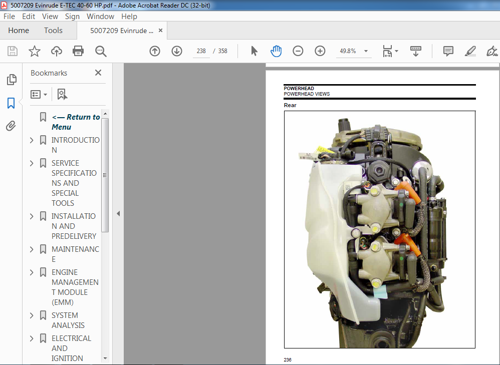
Rear 238
Top 239
Top, Rope Start Models 240
MIDSECTION 241
SERVICE CHART 242
CLEANING AND INSPECTION 245
General 245
Clamp Screw 245
Exhaust Housing 245
EXHAUST HOUSING 246
Removal 246
Servicing 247
Installation 248
STERN BRACKET-Power Tilt Models 249
Disassembly 249
Assembly 250
STERN BRACKET- Manual Tilt Models 251
Disassembly 251
Assembly 254
Tilt Assist Cylinder (Optional) 257
STEERING HANDLE 258
Removal 258
Disassembly 259
Inspection 260
Assembly 260
Installation 262
MIDSECTION AND TILLER ADJUSTMENTS 264
Steering Friction Adjustment 264
Throttle Friction Adjustment 264
GEARCASE 265
SERVICE CHART 266
PROPELLER 267
Inspection 267
LUBRICANT 267
Draining 267
Inspection 267
Filling 268
LEAK TEST 268
REMOVAL AND INSTALLATION 269
Removal 269
Installation 270
WATER PUMP 271
Disassembly 271
Inspection 271
Assembly 272
SHIFT ROD ADJUSTMENT 274
DISASSEMBLY 274
Pre-Disassembly Inspection 274
Propeller Shaft Bearing Housing Removal 275
Pinion Gear and Driveshaft Removal 276
Shift Housing, Gear and Propeller Shaft Removal 277
BEARING AND SEAL REMOVAL 278
Shift Housing 278
Pinion Gear Bearing 279
Water Intake Screen 280
Driveshaft Bearing Housing 280
Propeller Shaft Bearing Housing 280
BEARING AND SEAL INSTALLATION 282
Shift Housing 282
Water Intake Screen 283
Pinion Gear Bearing 283
Driveshaft Bearing Housing 284
Propeller Shaft Bearing Housing 284
DRIVESHAFT SHIMMING 285
ASSEMBLY 287
Shift Housing, Gear, and Propeller Shaft Installation 287
Shift Rod Housing Installation 287
Pinion Gear and Driveshaft Installation 288
Propeller Shaft Bearing Housing and Gear Installation 289
TRIM AND TILT 291
SYSTEM DESCRIPTION 292
ROUTINE INSPECTIONS 293
General 293
Reservoir Fluid 293
Manual Release Valve 293
Stern Brackets 293
ELECTRICAL CIRCUIT TESTS 294
Relay Testing 294
Trim and Tilt Motor Current Draw Tests 294
Trim and Tilt Motor No Load Test 295
Trim Gauge Test 295
Trim Sender Test 296
SERVICING 296
Removal 296
Disassembly 297
Assembly 298
Installation 299
ADJUSTMENTS 300
MANUAL STARTER 301
SERVICE CHART 302
REMOVAL 303
DISASSEMBLY 303
CLEANING AND INSPECTION 305
ASSEMBLY 305
INSTALLATION 309
NOTES 310
Technician’s Notes 310
Related Documents 310
SAFETY 311
TABLE OF CONTENTS 311
MARINE PRODUCTS AND THE SAFETY OF PEOPLE WHO USE THEM 313
Outboard Shift Systems and Safety 314
Outboard Speed Control System and Safety 315
Outboard Steering Control System and Safety 316
Outboard Fuel, Electrical System, and Safety 318
Outboard Mounting System and Safety 321
If weakened, parts could fail later on the water, when not expected 322
Outboard Hydraulic Tilt/Trim Shock Absorption System and Safety 323
Outboard Emergency Stop System and Safety 324
Summing up 326
MARINE PRODUCTS AND THE SAFETY OF PEOPLE WHO FIX THEM 327
Handling Outboards 327
Handling Lead/Acid Batteries 331
Gasoline – Handle With Care! 332
Hazardous Products 333
Safety Awareness Test 334
INDEX 335
TROUBLE CHECK CHART 343
OUTBOARD WILL NOT START 343
OUTBOARD WILL NOT START 344
OUTBOARD HARD TO START 345
OUTBOARD WILL NOT SHUT OFF 346
OUTBOARD STARTS AND STALLS 346
OUTBOARD STARTS, LOW MAXIMUM RPM 347
EXCESSIVE SMOKING 347
OUTBOARD SURGES, RUNS ROUGH 348
DIAGRAMS 349<— Return to Menu 0
INTRODUCTION 7
MODELS COVERED IN THIS MANUAL 8
Identifying Model and Serial Numbers 8
MODEL DESIGNATION 9
TYPICAL PAGE – A 10
TYPICAL PAGE – B 11
TYPICAL PAGE – C 12
TYPICAL PAGE – D 13
ABBREVIATIONS USED IN THIS MANUAL 14
Units of Measurement 14
List of Abbreviations 14
ENGINE EMISSIONS INFORMATION 15
Manufacturer’s Responsibility 15
Dealer’s Responsibility 15
Owner’s Responsibility 15
EPA Emission Regulations 15
PRODUCT REFERENCE AND ILLUSTRATIONS 16
SYMBOLS 16
Electrical 16
Values 17
NOTES 18
Technician’s Notes 18
Related Documents 18
SERVICE SPECIFICATIONS AND SPECIAL TOOLS 19
TECHNICAL DATA 20
STANDARD TORQUE SPECIFICATIONS 22
SPECIAL TOOLS 23
Electrical / Ignition 23
Fuel System 24
Gearcase 25
Powerhead 26
Starter 27
Universal 28
SHOP AIDS 30
INSTALLATION AND PREDELIVERY 33
BOAT RIGGING 34
Remote Controls 34
Battery Installation 36
Battery Switches and Multiple Batteries 37
Battery and Switch Wiring Diagrams 39
Fuel System Requirements 41
Cable and Hose Installation 43
OUTBOARD INSTALLATION 48
Hull Preparation 48
Transom Measuring and Drilling 49
Drilling and Hardware Diagrams 52
Lifting the Outboard 54
Steering Systems 54
Outboard Mounting 56
OUTBOARD RIGGING 58
Cable, Hose, and Wire Routing 58
Control Cable Adjustments 58
Electrical Harness Connections 60
Water Pressure Gauge 60
FUEL AND OIL PRIMING 61
Fuel Requirements 61
Fuel System Priming 62
Oil Requirements 63
Oil Injection Rate 63
SystemCheck Low Oil Warning Test 63
Oil Supply Priming 64
Break-In Oiling 64
BEFORE START-UP 65
Gearcase Lubricant 65
Oil Level 65
Trim and Tilt Fluid 65
RUNNING CHECKS 66
SystemCheck Operation 66
Fuel System 66
Emergency Stop / Key Switch 66
Remote Control Operation 66
Start-In-Gear Prevention 66
Tachometer Pulse Setting 67
Water Pump Overboard Indicator 67
Operating Temperature 67
Idle Speed 67
Break-In 67
PROPELLERS 68
Propeller Selection 68
Propeller Hardware Installation 69
FINAL ADJUSTMENTS 70
Trim Sending Unit Adjustment 70
Trim Tab Adjustment 71
Dual-Outboard Alignment 72
MAINTENANCE 73
INSPECTION AND MAINTENANCE SCHEDULE 74
ANTI-CORROSION PROTECTION 75
Sacrificial Anodes 75
Testing Procedure – Continuity 75
Metallic Component Protection 75
Exterior Finishes 75
COOLING SYSTEM 76
Flushing 76
Water Intake Screens 77
Additional Maintenance 77
LUBRICATION 77
Steering System 77
Swivel Bracket and Trailering Bracket 78
Tilt Tube 78
Throttle and Shift Linkage 78
Propeller Shaft 79
Gearcase Lubricant 79
Trim and Tilt 80
BATTERY AND BATTERY CONNECTIONS 80
FUEL AND OIL SYSTEMS 81
Fuel Filter 81
Oil Reservoir 81
Air Silencer 81
Hoses and Connections 81
SPARK PLUGS 82
Indexing 82
STORAGE 83
Fuel System Treatment 83
Internal Engine Treatment 83
Additional Recommendations 84
PRE-SEASON SERVICE 84
Outboard Mounting Bolts 84
Gearcase Lubricant 84
Battery(s) 84
Power Trim and Tilt 84
Operational Checks 84
SUBMERGED ENGINES 85
Engine Dropped Overboard (Not Running) 85
Engine Dropped Overboard (Running) 85
Engine Dropped Overboard (In Salt Water) 85
Prolonged Submersion (Fresh or Salt Water) 85
NOTES 86
Technician’s Notes 86
Related Documents 86
ENGINE MANAGEMENT MODULE (EMM) 87
DESCRIPTION 88
EMM Functions 88
EMM Connections 88
SENSORS AND FUNCTIONS 89
Internal Sensors 89
External Sensors 90
Internal Functions 92
EMM INPUTS AND OUTPUTS DIAGRAM 93
S A F E WARNING SYSTEM 94
Activation 94
Recovery 94
SHUTDOWN MODE 94
EMM DIAGNOSTICS 95
LED Indicators 95
Diagnostic Software Program 96
Communication 96
Program Information 97
Service Codes (Faults) 97
Static Tests 98
Dynamic Tests 99
Oil Control 100
Starter Mode (Tiller/Remote Programming) 100
Timing Verification 100
TPS Calibration 101
Idle Speed 101
Fuel Injector Servicing 101
Fuel Control Adjustment 102
Reports 102
Software Replacement 103
EMM Transfer 103
SystemCheck ENGINE MONITOR 103
System Self-Test 104
Service Mode 104
Engine Running 104
SYSTEM ANALYSIS 105
ELECTRICAL CONNECTIONS 106
GROUND CIRCUITS 108
Test Procedure 108
FUSE 108
EMM DIAGNOSTICS 109
LED Indicators 109
Software Programs 109
DIAGNOSTIC PROCEDURES 110
Symptoms 111
SPECIALIZED TEST PROCEDURES 112
Dynamic Tests 112
Testing with Timing Light 112
Inductive Amp Meter Test 113
Engine Monitoring Information 113
Voltage Testing 114
START CIRCUIT 114
Electric Starter Operation 114
Starter Solenoid Activation 115
IGNITION AND ELECTRICAL CIRCUITS 116
Stop Circuit 116
Neutral Switch 116
Stator Output Voltage 116
EMM 116
Crankshaft Position Sensor 116
Alternator Output Voltage 116
Capacitor 116
Ignition Power Supply to EMM 116
Ignition Primary Voltage 116
Ignition Coil 116
IGNITION OUTPUT 117
Wiring Inspection 117
Ignition Voltage 117
System Voltage 118
Static Spark Test 118
Running Ignition Tests 119
Ignition Primary Circuit Resistance Test 120
Crankshaft Position Sensor (CPS) Test 120
FUEL DELIVERY 121
Manifold Pressure Test 121
Vapor Separator Checks 122
Fuel Delivery to Lift Pump 122
FUEL INJECTOR OPERATION 122
Neutral Switch 122
Static Tests 122
Dynamic Tests 123
EXHAUST WATER VALVE 124
Static Test 124
Dynamic Test 124
ELECTRICAL AND IGNITION 125
SERVICE CHART 126
DASH CONNECTIONS, INSTRUMENT HARNESS 128
IGNITION SYSTEM TESTS 129
Sensor Resistance Tests 129
Ignition Coil Tests 130
Stator Tests 131
Capacitor Test 132
EXHAUST WATER VALVE TEST 132
CHARGING SYSTEM TESTS 132
12 V Charging Circuit 132
55 V Alternator Circuit 133
SystemCheck CIRCUIT TESTS 134
Gauge Self-Test Check 134
CHECK ENGINE Circuit Test 135
WATER TEMP/ HOT Circuit Test 135
LOW OIL Circuit Test 136
NO OIL Circuit Test 136
REMOTE CONTROL SWITCH TESTS 136
Key Switch Test 136
Neutral Start Circuit Test 137
Neutral Start Switch Test 137
Emergency Stop Switch Test 138
ELECTRIC STARTER TESTS 138
Starter Solenoid Test 138
No Load Current Draw Test 139
TILT/TRIM RELAY TEST 140
Operation 140
Test Procedure 140
TACHOMETER CIRCUIT TESTS 141
FLYWHEEL SERVICING 142
Removal 142
Installation 143
TIMING ADJUSTMENTS 144
Timing Pointer 144
Timing Verification 145
TPS Calibration 145
SPARK PLUGS 146
Inspection 146
Indexing 146
ELECTRIC STARTER SERVICING 147
Removal 147
Disassembly 147
Cleaning and Inspection 148
Assembly 149
Installation 150
CONNECTOR SERVICING 151
DEUTSCH Connectors 151
AMP Connectors 152
Packard † Connectors 154
NOTES 156
Technician’s Notes 156
Related Documents 156
FUEL SYSTEM 157
SERVICE CHART 158
COMPONENTS 160
Fuel Lift Pump 160
Fuel Filter 160
Vapor Separator 160
Fuel Circulation Pump 162
Fuel Manifolds 162
Fuel Injectors 163
FUEL SYSTEM HOSE ROUTING 164
DIRECT INJECTION ELECTRICAL CIRCUITS 165
Injector / Circulation Pump Circuits Diagram 165
FUEL COMPONENT TESTS 166
Injectors 166
Fuel Supply 167
FUEL COMPONENT SERVICING 170
Relieving Fuel System Pressure 170
Fuel Filter 171
Fuel Lift Pump 171
Vapor Separator 172
Fuel Injectors 172
Fuel Manifolds 176
INTAKE MANIFOLD 176
Removal 176
Disassembly 176
Inspection 177
Assembly 177
Installation 178
OILING SYSTEM 179
SERVICE CHART 180
COMPONENTS 181
Oil Tank Assembly 181
Electrical Circuit (55 V) 182
SystemCheck LOW and NO OIL Warning Signals 182
Oiling System Electrical Diagram 183
Cylinder and Crankcase 184
Oil Supply and Distribution Diagram 184
Oil Recirculation System 185
Recirculation Hose Diagram 185
PRIMING 186
OILING RATES 186
Oil Injection Rate 186
Break-in Oiling 186
OILING SYSTEM TESTS 187
Oil Injection Pump Static Test 187
Oil Injection Pump Voltage Test 187
Oil Injection Pump Circuit Resistance Test 188
Oil Flow Tests 188
Oil-to-Fuel Check Valve Test 190
LOW OIL Sending Unit Test 190
NO OIL Warning Test 190
OIL COMPONENT SERVICING 191
Oil Distribution Hoses 191
Oil Tank Assembly 192
COOLING SYSTEM 193
HOSE ROUTING AND WATER FLOW DIAGRAM 194
ENGINE TEMPERATURE CHECK 195
Software Method 195
Pyrometer Method 195
Idle Operating Temperature Troubleshooting (Below Range) 196
COMPONENTS 197
General Description 197
Water Pump and Intakes 197
Exhaust Housing 198
Pressure Relief Valve 198
Thermostat 198
Block Venting 199
Water Pressure Connection 199
OPERATION 199
Cylinder Block / Cylinder Head Cooling 199
EMM and Vapor Separator Cooling 200
THERMOSTAT SERVICING 200
Disassembly 200
Inspection 201
Assembly 201
PRESSURE RELIEF VALVE SERVICING 201
Disassembly 201
Inspection 202
Assembly 202
POWERHEAD 203
SERVICE CHART 204
GENERAL 206
Cylinder Compression Testing 206
Retaining Ring Pliers 206
REMOVAL 207
DISASSEMBLY 209
General 209
Shift Linkage 209
Throttle Linkage 209
Crankcase 210
Cylinder Head 211
Connecting Rods and Pistons 211
Crankshaft 212
CLEANING 214
INSPECTION 215
Cylinder Head 215
Crankshaft 216
Cylinder Bore 216
Pistons 216
Piston Rings 216
Bearings 217
ASSEMBLY 218
Crankshaft 218
Pistons and Connecting Rods 220
Cylinder Head 222
Crankshaft and Connecting Rods 223
Crankcase 226
Shift Linkage 228
Throttle Linkage 229
General 229
INSTALLATION 230
POWERHEAD VIEWS 234
Port Short Block 234
Starboard Short Block 234
Port Dressed Powerhead 235
Starboard Dressed Powerhead 235
Port Rope Start Models 236
Starboard Rope Start Models 236
Front 237
Rear 238
Top 239
Top, Rope Start Models 240
MIDSECTION 241
SERVICE CHART 242
CLEANING AND INSPECTION 245
General 245
Clamp Screw 245
Exhaust Housing 245
EXHAUST HOUSING 246
Removal 246
Servicing 247
Installation 248
STERN BRACKET-Power Tilt Models 249
Disassembly 249
Assembly 250
STERN BRACKET- Manual Tilt Models 251
Disassembly 251
Assembly 254
Tilt Assist Cylinder (Optional) 257
STEERING HANDLE 258
Removal 258
Disassembly 259
Inspection 260
Assembly 260
Installation 262
MIDSECTION AND TILLER ADJUSTMENTS 264
Steering Friction Adjustment 264
Throttle Friction Adjustment 264
GEARCASE 265
SERVICE CHART 266
PROPELLER 267
Inspection 267
LUBRICANT 267
Draining 267
Inspection 267
Filling 268
LEAK TEST 268
REMOVAL AND INSTALLATION 269
Removal 269
Installation 270
WATER PUMP 271
Disassembly 271
Inspection 271
Assembly 272
SHIFT ROD ADJUSTMENT 274
DISASSEMBLY 274
Pre-Disassembly Inspection 274
Propeller Shaft Bearing Housing Removal 275
Pinion Gear and Driveshaft Removal 276
Shift Housing, Gear and Propeller Shaft Removal 277
BEARING AND SEAL REMOVAL 278
Shift Housing 278
Pinion Gear Bearing 279
Water Intake Screen 280
Driveshaft Bearing Housing 280
Propeller Shaft Bearing Housing 280
BEARING AND SEAL INSTALLATION 282
Shift Housing 282
Water Intake Screen 283
Pinion Gear Bearing 283
Driveshaft Bearing Housing 284
Propeller Shaft Bearing Housing 284
DRIVESHAFT SHIMMING 285
ASSEMBLY 287
Shift Housing, Gear, and Propeller Shaft Installation 287
Shift Rod Housing Installation 287
Pinion Gear and Driveshaft Installation 288
Propeller Shaft Bearing Housing and Gear Installation 289
TRIM AND TILT 291
SYSTEM DESCRIPTION 292
ROUTINE INSPECTIONS 293
General 293
Reservoir Fluid 293
Manual Release Valve 293
Stern Brackets 293
ELECTRICAL CIRCUIT TESTS 294
Relay Testing 294
Trim and Tilt Motor Current Draw Tests 294
Trim and Tilt Motor No Load Test 295
Trim Gauge Test 295
Trim Sender Test 296
SERVICING 296
Removal 296
Disassembly 297
Assembly 298
Installation 299
ADJUSTMENTS 300
MANUAL STARTER 301
SERVICE CHART 302
REMOVAL 303
DISASSEMBLY 303
CLEANING AND INSPECTION 305
ASSEMBLY 305
INSTALLATION 309
NOTES 310
Technician’s Notes 310
Related Documents 310
SAFETY 311
TABLE OF CONTENTS 311
MARINE PRODUCTS AND THE SAFETY OF PEOPLE WHO USE THEM 313
Outboard Shift Systems and Safety 314
Outboard Speed Control System and Safety 315
Outboard Steering Control System and Safety 316
Outboard Fuel, Electrical System, and Safety 318
Outboard Mounting System and Safety 321
If weakened, parts could fail later on the water, when not expected 322
Outboard Hydraulic Tilt/Trim Shock Absorption System and Safety 323
Outboard Emergency Stop System and Safety 324
Summing up 326
MARINE PRODUCTS AND THE SAFETY OF PEOPLE WHO FIX THEM 327
Handling Outboards 327
Handling Lead/Acid Batteries 331
Gasoline – Handle With Care! 332
Hazardous Products 333
Safety Awareness Test 334
INDEX 335
TROUBLE CHECK CHART 343
OUTBOARD WILL NOT START 343
OUTBOARD WILL NOT START 344
OUTBOARD HARD TO START 345
OUTBOARD WILL NOT SHUT OFF 346
OUTBOARD STARTS AND STALLS 346
OUTBOARD STARTS, LOW MAXIMUM RPM 347
EXCESSIVE SMOKING 347
OUTBOARD SURGES, RUNS ROUGH 348
DIAGRAMS 349
VIDEO PREVIEW OF THE MANUAL:

IMAGES PREVIEW OF THE MANUAL:


PLEASE NOTE:
- This is the SAME manual used by the dealers to troubleshoot any faults in your vehicle. This can be yours in 2 minutes after the payment is made.
- Contact us at [email protected] should you have any queries before your purchase or that you need any other service / repair / parts operators manual.


