

2007 Evinrude 115 150 175 200 HP Service Manual
FILE DETAILS:
2007 Evinrude 115 150 175 200 HP Service Manual
Language: English
Size: 43.8 MB
Pages: 443
Format: PDF
Downloadable: YES
DESCRIPTION:
2007 Evinrude 115 150 175 200 HP Service Manual
SAFETY INFORMATIONS:
Always follow common shop safety practices. If you have not had training related to common shop safety practices, you should do so to protect yourself, as well as the people around you. It is understood that this manual may be translated into other languages. In the event of any discrepancy, the English version shall prevail. To reduce the risk of personal injury, safety warnings are provided at appropriate times throughout the manual. DO NOT make any repairs until you have read the instructions and checked the pictures relating to the repairs.
- Be careful, and never rush or guess a service procedure. Human error is caused by many factors: carelessness, fatigue, overload, preoccupation, unfamiliarity with the product, and drugs and alcohol use, to name a few. Damage to a boat and outboard can be fixed in a short period of time, but injury or death has a lasting effect.
- When replacement parts are required, use Evinrude/Johnson Genuine Parts or parts with equivalent characteristics, including type, strength and material. Using substandard parts could result in injury or product malfunction.
- Torque wrench tightening specifications must be strictly followed. Replace any locking fastener (locknut or patch screw) if its locking feature becomes weak. Definite resistance to turning must be felt when reusing a locking fastener.
- If replacement is specified or required because the locking fastener has become weak, use only authorized Evinrude/Johnson Genuine Parts. If you use procedures or service tools that are not recommended in this manual, YOU ALONE must decide if your actions might injure people or damage the outboard.
TABLE OF CONTENTS:
2007 Evinrude 115 150 175 200 HP Service Manual
<— Return to Menu 0
INTRODUCTION 7
MODELS COVERED IN THIS MANUAL 8
Identifying Model and Serial Numbers 8
MODEL DESIGNATION 9
TYPICAL PAGE – A 10
TYPICAL PAGE – B 11
TYPICAL PAGE – C 12
TYPICAL PAGE – D 13
ABBREVIATIONS USED IN THIS MANUAL 14
Units of Measurement 14
List of Abbreviations 14
ENGINE EMISSIONS INFORMATION 15
Manufacturer’s Responsibility 15
Dealer’s Responsibility 15
Owner’s Responsibility 15
EPA Emission Regulations 15
PRODUCT REFERENCE AND ILLUSTRATIONS 16
SYMBOLS 16
Electrical 16
Values 17
NOTES 18
Technician’s Notes 18
Related Documents 18
SERVICE SPECIFICATIONS AND SPECIAL TOOLS 19
TECHNICAL DATA 20
STANDARD TORQUE SPECIFICATIONS 22
SPECIAL TOOLS 23
Diagnostics 23
Universal 23
Electrical / Ignition 24
Fuel/Oil Systems 25
Powerhead 26
Gearcase 27
Trim and Tilt 29
SHOP AIDS 30
NOTES 34
Technician’s Notes 34
Related Documents 34
INSTALLATION AND PREDELIVERY 35
BOAT RIGGING 36
Remote Controls 36
Battery Installation 38
Battery Switches and Multiple Batteries 39
Auxiliary Battery Charge Isolator 40
Battery and Switch Wiring Diagrams 41
Fuel System Requirements 43
Oiling System Set-Up 45
Cable and Hose Installation 48
OUTBOARD INSTALLATION 53
Hull Preparation 53
Transom Measuring and Drilling 54
Drilling and Hardware Diagrams 57
Lifting the Outboard 58
Steering Systems 58
Outboard Mounting 60
OUTBOARD RIGGING 61
Cable, Hose, and Wire Routing 61
Control Cable Installation 62
Electrical Harness Connections 64
Water Pressure Gauge 65
CANbus Connections 65
FUEL AND OIL PRIMING 67
Fuel Requirements 67
Fuel System Priming 68
Oil Requirements 68
Oil Injection Rate 69
Break-In Oiling 69
SystemCheck Low Oil Warning 70
Oil Supply Priming 70
BEFORE START-UP 72
Gearcase Lubricant 72
Oil Level 72
Trim and Tilt Fluid 72
RUNNING CHECKS 73
SystemCheck Operation 73
Fuel System 73
Emergency Stop / Key Switch 73
Remote Control Operation 73
Start-In-Gear Prevention 73
Tachometer Pulse Setting 74
Water Pump Overboard Indicator 74
Operating Temperature 74
Idle Speed 74
Break-In 74
PROPELLERS 75
Propeller Selection 75
Propeller Hardware Installation 76
FINAL ADJUSTMENTS 77
Tilt Limit Switch Adjustment 77
Trim Sending Unit Adjustment 78
Trim Tab Adjustment 79
Dual-Outboard Alignment 80
MAINTENANCE 81
INSPECTION AND MAINTENANCE SCHEDULE 82
ANTI-CORROSION PROTECTION 83
Sacrificial Anodes 83
Testing Procedure – Continuity 83
Metallic Component Protection 83
Exterior Finishes 83
COOLING SYSTEM 84
Flushing 84
Water Intake Screens 85
Additional Maintenance 85
LUBRICATION 85
Steering System 85
Swivel Bracket and Trailering Bracket 86
Tilt Tube 86
Throttle and Shift Linkage 86
Propeller Shaft 87
Gearcase Lubricant 87
Trim and Tilt 88
BATTERY AND BATTERY CONNECTIONS 89
FUEL AND OIL SYSTEMS 89
Fuel Filter 89
Oil Filters and Oil Reservoir 90
Air Silencer 90
Hoses and Connections 90
SPARK PLUGS 91
Indexing 91
EXHAUST PRESSURE FITTING 92
Operation Test 92
Cleaning 92
STORAGE 93
Fuel System Treatment 93
Internal Engine Treatment 93
Additional Recommendations 94
PRE-SEASON SERVICE 94
Outboard Mounting Bolts 94
Gearcase Lubricant 94
Battery(s) 94
Power Trim and Tilt 94
Operational Checks 94
SUBMERGED ENGINES 95
Engine Dropped Overboard (Not Running) 95
Engine Dropped Overboard (Running) 95
Engine Dropped Overboard (In Salt Water) 95
Prolonged Submersion (Fresh or Salt Water) 95
NOTES 96
Technician’s Notes 96
Related Documents 96
ENGINE MANAGEMENT MODULE (EMM) 97
DESCRIPTION 98
EMM Functions 98
EMM Connections 98
SENSORS AND FUNCTIONS 99
Internal Sensors 99
External Sensors 100
Internal Functions 103
EMM INPUTS AND OUTPUTS DIAGRAM 104
S A F E WARNING SYSTEM 105
Initiation 105
Recovery 105
SHUTDOWN MODE 105
EMM DIAGNOSTICS 106
LED Indicators 106
Diagnostic Software Program 107
Communication 107
Program Information 108
Service Codes (Faults) 108
Static Tests 109
Dynamic Tests 110
Oil Control 111
Timing Verification 111
TPS Calibration 112
Fuel Injector Servicing 112
Fuel Control Adjustment 112
Reports 113
Software Replacement 113
EMM Transfer 113
SystemCheck ENGINE MONITOR 114
Gauges 114
System Self-Test 114
Service Mode 114
Engine Running 114
SYSTEM ANALYSIS 115
ELECTRICAL CONNECTIONS 116
GROUND CIRCUITS 118
Test Procedure 118
FUSE 118
EMM DIAGNOSTICS 119
LED Indicators 119
Software Programs 119
DIAGNOSTIC PROCEDURES 120
Symptoms 121
SPECIALIZED TEST PROCEDURES 122
Dynamic Tests 122
Testing with Timing Light 122
Inductive Amp Meter Test 123
Engine Monitoring Information 123
Voltage Testing 124
START CIRCUIT 124
Electric Starter Operation 124
Starter Solenoid Activation 125
Start Circuit Diagram 127
IGNITION AND ELECTRICAL CIRCUITS 128
Stop Circuit 128
Battery 128
Stator Output Voltage 128
EMM 128
Crankshaft Position Sensor 128
Alternator Output/System Voltage 128
Capacitor 128
Ignition Primary Voltage 128
Ignition Coil 128
IGNITION OUTPUT 129
Wiring Inspection 129
Ignition Voltage 129
System Voltage 130
Static Spark Test 130
Running Ignition Tests 131
Ignition Primary Circuit Resistance Test 132
Crankshaft Position Sensor (CPS) Test 132
FUEL DELIVERY 133
Manifold Pressure Test 133
Vapor Separator Checks 134
Fuel Delivery to Lift Pump 134
FUEL INJECTOR OPERATION 134
Static Tests 134
Dynamic Tests 135
EXHAUST VALVE (V4 MODELS) 136
ELECTRICAL AND IGNITION 137
SERVICE CHART 138
DASH CONNECTIONS, INSTRUMENT HARNESS 140
SENSOR RESISTANCE TESTS 141
Crankshaft Position Sensor (CPS) Test 141
Throttle Position Sensor (TPS) Test 141
Engine Temperature Sensor Test 142
Air Temperature Sensor (AT) Test 142
CAPACITOR TEST 142
IGNITION COIL TESTS 143
Primary Winding Resistance Test 143
Secondary Winding Resistance Test 143
STATOR TESTS 143
Stator Resistance Tests 143
Stator Voltage Output Test 144
CHARGING SYSTEM TESTS 144
12 V Charging Circuit 144
55 V Alternator Circuit 145
Auxiliary Battery – Charge Wire 146
SystemCheck CIRCUIT TESTS 147
Gauge Self-Test Check 147
CHECK ENGINE Circuit Test 148
WATER TEMP/ HOT Circuit Test 148
LOW OIL Circuit Test 149
NO OIL Circuit 149
REMOTE CONTROL SWITCH TESTS 149
Key Switch Test 149
Neutral Start Circuit Test 150
Neutral Start Switch Test 150
Emergency Stop Switch Test 151
TACHOMETER CIRCUIT TESTS 151
ELECTRIC STARTER TESTS 152
Starter Solenoid Test 152
No Load Current Draw Test 152
TILT/TRIM RELAY TEST 153
Operation 153
Test Procedure 154
EXHAUST VALVE RELAY TESTS 154
Operation 155
EMM SERVICING 155
Removal 155
Installation 156
FLYWHEEL AND STATOR SERVICING 156
Flywheel Removal 156
Stator Service 158
Flywheel Installation 158
TIMING ADJUSTMENTS 159
Timing Pointer 159
Timing Verification 161
TPS CALIBRATION 161
SPARK PLUGS 162
Inspection 162
Indexing 162
ELECTRIC STARTER SERVICING 163
Removal 163
Disassembly 163
Cleaning and Inspection 166
Assembly 167
Installation 169
CONNECTOR SERVICING 170
DEUTSCH Connectors 170
AMP Connectors 171
Packard † Connectors 173
FUEL SYSTEM 175
SERVICE CHART 176
COMPONENTS 179
Fuel Lift Pump 179
Fuel Filter 179
Vapor Separator 180
Fuel Circulation Pump 181
Fuel Manifolds 181
Fuel Injectors 182
FUEL SYSTEM HOSE ROUTING 183
DIRECT INJECTION ELECTRICAL CIRCUITS 184
Injector / Circulation Pump Circuits Diagram 185
FUEL COMPONENT TESTS 186
Fuel Injectors 186
Fuel Supply 187
FUEL COMPONENT SERVICING 191
Relieving Fuel System Pressure 191
In-Line Fuel Filter 192
Optional Fuel Filter 192
Fuel Lift Pump 193
Vapor Separator 193
Fuel Manifolds 194
Fuel Injectors 195
INTAKE MANIFOLD 198
Removal 198
Disassembly 198
Inspection 199
Assembly 199
Installation 199
OILING SYSTEM 201
SERVICE CHART 202
COMPONENTS 203
Oil Tank 203
Oil Injection Pump 203
Oil Pressure Sensor 204
Electrical Circuit (55 V) 204
Oil Injection Pump Diagram 205
Oiling System Electrical Diagram 206
SystemCheck, I-Command and EMM Oiling System Warnings 207
Cylinder and Crankcase 207
Oil Supply and Distribution Diagrams – V6 208
Oil Supply and Distribution Diagrams – V4 210
Oil Recirculation System 212
Recirculation Hose Routings and Check Valve Diagrams – V6 213
Recirculation Hose Routings and Check Valve Diagrams – V4 215
PRIMING 217
Oil Hose Connections 217
Oil Distribution Manifold Priming 217
OILING RATES 219
Oil Injection Rate 219
XD100 Outboard Oil Decal 219
Break-in Oiling 219
OILING SYSTEM TESTS 220
Oil Injection Pump Static Test 220
Oil Injection Pump Voltage Test 220
Oil Injection Pump Circuit Resistance Test 221
Oil Supply Vacuum Test 222
Oil Injection Pump Function Test 222
Oil Injection Fittings Flow Test 223
LOW OIL Sending Unit Test 223
OIL COMPONENT SERVICING 224
Oil Distribution Hoses 224
Oil Injection Pump 225
COOLING SYSTEM 227
HOSE ROUTING AND WATER FLOW DIAGRAMS 228
HOSE ROUTING AND WATER FLOW DIAGRAMS 229
ENGINE TEMPERATURE CHECK 230
Software Method 230
Pyrometer Method 230
Idle Operating Temperature Troubleshooting (Below Range) 231
COMPONENTS 232
General Description 232
Water Pump and Intakes 232
Water Supply Tube 232
Adapter/Inner Exhaust Housing 233
Pressure Relief Valve 233
Thermostats 233
Block Venting 233
OPERATION 234
Cylinder Block / Cylinder Head Cooling 234
Vapor Separator and EMM Cooling 234
THERMOSTAT SERVICING 235
Disassembly 235
Inspection 235
Assembly 235
PRESSURE RELIEF VALVE SERVICING 235
Disassembly 235
Inspection 236
Assembly 236
POWERHEAD 237
SERVICE CHART 238
GENERAL 240
Cylinder Compression Testing 240
Retaining Ring Pliers 240
REMOVAL 241
DISASSEMBLY 243
General 243
Crankcase 244
Cylinder Head 245
Connecting Rods and Pistons 245
Crankshaft 247
CLEANING 249
INSPECTION 250
Cylinder Head 250
Crankshaft 250
Cylinder Bore 251
Pistons 251
Piston Rings 251
Bearings 252
ASSEMBLY 252
Crankshaft 252
Pistons and Connecting Rods 254
Cylinder Head 256
Crankshaft and Connecting Rods 257
Crankcase 260
General 261
UPPER MOUNT SERVICING 263
Removal 263
Installation 264
INSTALLATION 264
POWERHEAD VIEWS 268
V4 Starboard – Hose Routings 268
V4 Port – Hose Routings 269
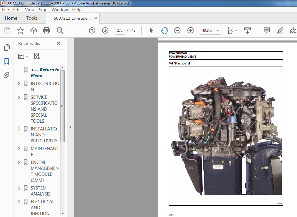
V4 Starboard 270
V4 Port 271
V4 Front 272
V4 Rear 273
Top – Hose Routings 274
V4 – V6 Top 275
V6 Starboard – Hose Routings 276
V6 Port – Hose Routings 277
V6 Starboard 278
V6 Port 279
V6 Front 280
V6 Rear 281
NOTES 282
Technician’s Notes 282
Related Documents 282
MIDSECTION 283
SERVICE CHART 284
TILT TUBE 287
Removal 287
Installation 288
EXHAUST HOUSING 289
Removal 289
Disassembly 290
Cleaning and Inspection 291
Assembly 291
Installation 294
STERN BRACKET 295
Removal 295
Disassembly 295
Assembly 297
EXHAUST RELIEF MUFFLER ASSEMBLY 300
GEARCASE 301
SERVICE CHART 302
GEARCASE TYPES 307
PROPELLER 308
Inspection 308
SHIFT INTERRUPT SWITCH 308
LUBRICANT 309
Draining 309
Inspection 309
Filling 309
LEAK TEST 310
REMOVAL AND INSTALLATION 310
Removal 310
Installation 311
WATER PUMP 313
Disassembly 313
Inspection 313
Assembly 314
SHIFT ROD ADJUSTMENT 316
DISASSEMBLY 316
Pre-Disassembly Inspection 316
Propeller Shaft Bearing Housing Removal 317
Pinion Gear and Driveshaft Removal 318
Driveshaft Service 322
Shift Housing, Gear and Propeller Shaft Removal 325
Water Intake Screens 325
GEARCASE HOUSING INSPECTION 325
BEARING AND SEAL REMOVAL 326
Shift Housing 326
Pinion Gear Bearing 327
Driveshaft Bearing Housing 328
Propeller Shaft Bearing Housing 328
BEARING AND SEAL INSTALLATION 329
Shift Housing 329
Pinion Gear Bearing 331
Driveshaft Bearing Housing 332
Propeller Shaft Bearing Housing 333
DRIVESHAFT SHIMMING 334
ASSEMBLY 336
Water Intake Screens 336
Shift Housing, Gear, and Propeller Shaft Installation 336
Shift Rod Housing Installation 336
Pinion Gear and Driveshaft Installation 337
Propeller Shaft Bearing Housing and Gear Installation 342
COUNTER ROTATION 343
Propeller Shaft Bearing Housing Removal 343
Shift Housing, Gear and Propeller Shaft Removal 343
Shift Housing Service 344
Propeller Shaft Bearing Housing and Forward Gear 347
Propeller Shaft Bearing Housing Seals and Bearings 352
Propeller Shaft Bearing Housing and Gear Installation 354
NOTES 356
Technician’s Notes 356
Related Documents 356
TRIM AND TILT 357
SERVICE CHART 358
SYSTEM DESCRIPTION 360
Manual Adjustment 360
Trailering Bracket And Tilt Support 360
MODES OF OPERATION (Three Piston System) 361
Trim-OUT / Tilt-UP Mode 361
2 361
Tilt-DOWN / Trim-IN Mode 362
Impact Relief 363
1 363
Shallow Water Drive Tilt Relief 364
Thermal Expansion Relief 364
Manual Release – UP 365
Manual Release – DOWN 366
ROUTINE INSPECTIONS 367
General 367
Reservoir Fluid 367
Manual Release Valve 367
Stern Brackets 367
TROUBLESHOOTING 368
FasTrak – Three Piston System 368
Single Piston System 371
ELECTRICAL CIRCUIT TESTS 372
Relay Testing 372
Trim and Tilt Motor Current Draw Tests 372
Trim and Tilt Motor No Load Test 373
Trim Gauge Test 374
Trim Sender Test 374
REMOVAL AND INSTALLATION 375
Removal 375
Installation 376
SERVICING – THREE PISTON SYSTEM 378
Disassembly 378
Tilt Piston Removal 380
Tilt Piston Identification 381
Tilt Piston Assembly 382
Tilt Rod Assembly 382
Trim Rod Removal 384
Trim Rod Assembly 385
Manifold and Reservoir Installation 386
Trim Rod Installation 387
Tilt Rod Installation 387
Motor Installation 388
SERVICING-SINGLE PISTON SYSTEM 390
Disassembly 390
Assembly 391
ADJUSTMENTS 392
SAFETY 393
TABLE OF CONTENTS 393
MARINE PRODUCTS AND THE SAFETY OF PEOPLE WHO USE THEM 395
Outboard Shift Systems and Safety 396
Outboard Speed Control System and Safety 397
Outboard Steering Control System and Safety 398
Outboard Fuel, Electrical System, and Safety 400
Outboard Mounting System and Safety 403
If weakened, parts could fail later on the water, when not expected 404
Outboard Hydraulic Tilt/Trim Shock Absorption System and Safety 405
Outboard Emergency Stop System and Safety 406
Summing up 408
MARINE PRODUCTS AND THE SAFETY OF PEOPLE WHO FIX THEM 409
Handling Outboards 409
Handling Lead/Acid Batteries 413
Gasoline – Handle With Care! 414
Hazardous Products 415
Safety Awareness Test 416
INDEX 417
TROUBLE CHECK CHART 427
OUTBOARD WILL NOT START 427
OUTBOARD WILL NOT START 428
OUTBOARD HARD TO START 429
OUTBOARD WILL NOT SHUT OFF 430
OUTBOARD STARTS AND STALLS 430
OUTBOARD STARTS, LOW MAXIMUM RPM 431
EXCESSIVE SMOKING 431
OUTBOARD SURGES, RUNS ROUGH 432
DIAGRAMS 433
VIDEO PREVIEW OF THE MANUAL:

IMAGES PREVIEW OF THE MANUAL:


PLEASE NOTE:
- This is the same manual used by the dealers to diagnose and troubleshoot your vehicle
- You will be directed to the download page as soon as the purchase is completed. The whole payment and downloading process will take anywhere between 2-5 minutes
- Need any other service / repair / parts manual, please feel free to contact [email protected] . We still have 50,000 manuals unlisted


