2005 Land Rover LR3 Electrical Circuit Diagrams Manual – PDF DOWNLOAD
$25.95
2005 Land Rover LR3 Electrical Circuit Diagrams Manual – PDF DOWNLOAD
Part No. LRE069_1 NAS
Description
2005 Land Rover LR3 Electrical Circuit Diagrams Manual – PDF DOWNLOAD
FILE DETAILS:
2005 Land Rover LR3 Electrical Circuit Diagrams Manual – PDF DOWNLOAD
Language : English
Pages :191
Downloadable : Yes
File Type : PDF
DESCRIPTION:
2005 Land Rover LR3 Electrical Circuit Diagrams Manual – PDF DOWNLOAD
Part No. LRE069_1 NAS
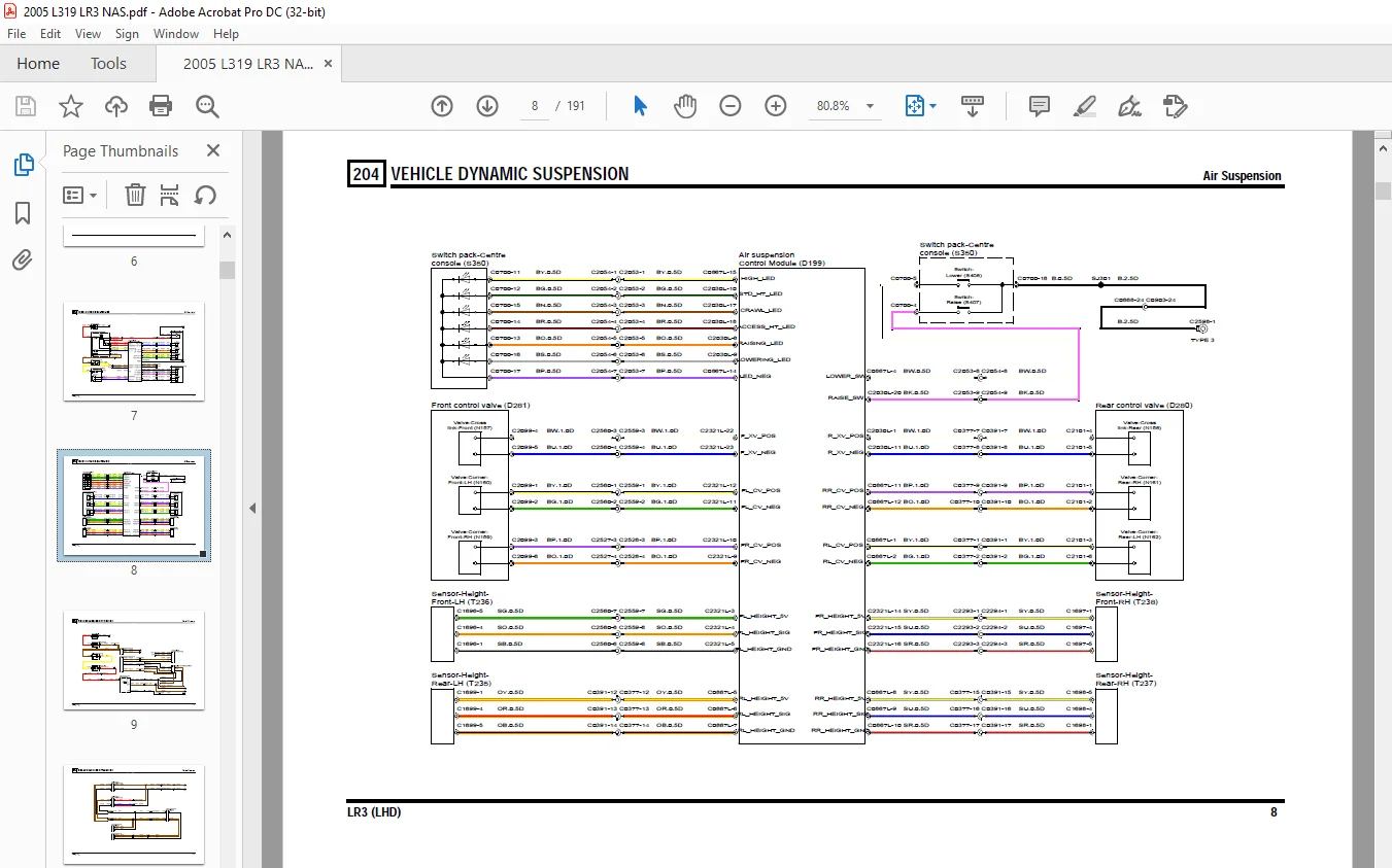
HOW TO USE THE CIRCUIT DIAGRAMS
- All of the information in this publication is intended for use in conjunction with the Electrical Library, which can be found using GTR.
- The sections in this publication are numbered to correspond with Workshop Manual information that can be located using GTR.
- Note: The Power and Earth distribution circuits can be found under section 414.
Power Distribution
- The Power Distribution diagram shows the connections from the battery to the engine, passenger, and where applicable, rear fuse box. It also shows the internal circuitry of the fuse boxes.
- The fuse box details are followed by independent functionally specific circuits and then a splices and centre taps section outlining the way in which internal harness splices and centre taps distribute power in the harnesses. This information should be used during diagnosis of electrical faults to check for symptoms in associated circuits and narrow down the search area
Earth Distribution
The earth distribution section comprises a number of Headers and Splices circuits. These are used in a similar manner to those in Power Distribution; to narrow the search area by checking for fault symptoms in associated circuits
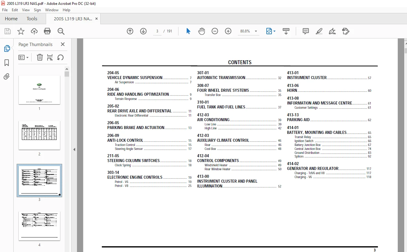
TABLE OF CONTENTS:
2005 Land Rover LR3 Electrical Circuit Diagrams Manual – PDF DOWNLOAD
LR3 Electrical Circuit Diagrams - North American Markets only....  1
VEHICLE DYNAMIC SUSPENSION.......................................  7
RIDE AND HANDLING OPTIMIZATION...................................  9
REAR DRIVE AXLE AND DIFFERENTIAL................................. 11
PARKING BRAKE AND ACTUATION...................................... 13
ANTI-LOCK CONTROL................................................ 15
STEERING COLUMN SWITCHES......................................... 18
ELECTRONIC ENGINE CONTROLS....................................... 19
AUTOMATIC TRANSMISSION........................................... 32
FOUR WHEEL DRIVE SYSTEMS......................................... 35
FUEL TANK AND FUEL LINES......................................... 37
AIR CONDITIONING................................................. 39
AUXILIARY CLIMATE CONTROL........................................ 46
CONTROL COMPONENTS............................................... 49
INSTRUMENT CLUSTER AND PANEL ILLUMINATION........................ 52
INSTRUMENT CLUSTER............................................... 57
HORN............................................................. 60
INFORMATION AND MESSAGE CENTRE................................... 61
PARKING AID...................................................... 62
BATTERY, MOUNTING AND CABLES..................................... 65
GENERATOR AND REGULATOR..........................................117
ENTERTAINMENT SYSTEM.............................................119
EXTERIOR LIGHTING................................................130
INTERIOR LIGHTING................................................144
MODULE COMMUNICATIONS NETWORK....................................147
ANTI-THEFT ALARM.................................................154
REAR VIEW MIRRORS................................................158
SEATING..........................................................164
GLASS, FRAMES AND MECHANISMS.....................................172
INSTRUMENT PANEL AND CONSOLE.....................................175
HANDLES, LOCKS, LATCHES AND ENTRY SYSTEMS........................177
WIPERS AND WASHERS...............................................182
ROOF OPENING PANEL...............................................187
SUPPLEMENTAL RESTRAINT SYSTEM....................................188
Questions? Email us: [email protected]
https://vimeo.com/889047038?share=copy
IMAGES PREVIEW OF THE MANUAL:
S.M