

1974-1975 Cessna 182 Parts Catalog Manual – PDF DOWNLOAD
IMAGES PREVIEW OF THE MANUAL:
DESCRIPTION:
1974-1975 Cessna 182 Parts Catalog Manual – PDF DOWNLOAD
INTRODUCTION.
This illustrated parts catalog has been prepared to aid
you in easily and quickly identifying parts of the models
covered herein.
This catalog features an index system consisting of:
l. An alphabetical index located in the front of the
catalog.
2. A numerical index located in the back of the
catalog, which Usts all parts and figures in
which they appear.
STANDARD PARTS.
Many parts having standard usage have been incorporated
into the Cessna Standard System. Parts in this
group are designated with the part number prefix “S”.
For standard hardware items such as Tinnerman nuts,
clamps, etc., “AN” and “NAS” numbers have been
used.
USABLE ON CODES ..•• Serial Ustings in this catalog
are noted by a letter code located in the usable on code
column which is the extreme right hand column of the
parts list page. Usable on codes are applicable only
to the figure on which they appear. The code letters
and the serials to which they apply are listed at the
end of the figure.
lf no usable on code appears opposite a first column
Usting of the figure, the usage is applicable to all
models and serials covered by this catalog. lf no
usable on code appears opposite any indented Usting
the usage is appUcable to all models and serials cov~
ered by the figure on which it appears.
Bold f~ce type serials appearing on certain figures are
for qu1ck reference to large blocks of ~irplanes.
NO~-INTERCHANGEABLE PARTS .••• When parts are
not 1_nterchangeable with earlier models, all parts
apphcable to the particular usage are Usted. The
letter code for the individual part usage is Usted in
the usable on column opposite each part. Care should
be exercised in determining proper serial when ordering
to insure receipt of correct part.
TABLE OF CONTENTS:
1974-1975 Cessna 182 Parts Catalog Manual – PDF DOWNLOAD
Menu – Cessna 182 Parts 74-76…………………………….. 0
Toolbar Help……………………………………………. 0
Parts Figures List (Links)……………………………….. 0
Cover Page……………………………………………… 1
Introduction……………………………………………. 3
Finish & Trim Plate……………………………………… 5
Upholstery & Interior Trim……………………………….. 9
Alphabetical Index………………………………………. 17
A – B………………………………………………. 18
B (cont) – C………………………………………… 19
C (cont) – E………………………………………… 20
E (cont) – F………………………………………… 21
F (cont) – H………………………………………… 22
I – M………………………………………………. 23
M (cont) – P………………………………………… 24
P (cont) – R………………………………………… 25
S………………………………………………….. 26
S (cont) – U………………………………………… 27
V – Z………………………………………………. 28
Parts Listing / Figures………………………………….. 29
1. Miscellaneous Bulk Items…………………………… 32
2. (Sheet 1) Placards, Nameplates & Exterior Markings……. 34
2. (Sheet 2) Placards, Nameplates & Exterior Markings……. 35
2. (Sheet 3) Placards, Nameplates & Exterior Markings……. 36
2. (Sheet 4) Placards, Nameplates & Exterior Markings……. 38
2. (Sheet 5) Placards, Nameplates & Exterior Markings……. 40
3. Wing Assembly Complete…………………………….. 42
4. Wing Structure Assembly……………………………. 46
5. Wing Leading Edge Assembly…………………………. 48
6. Wing Spar Assemblies………………………………. 50
7. Skins & Stringers Installation……………………… 52
8. Fuel Tank Installation…………………………….. 54
9. Fuel Tank Drain Valve Installation………………….. 57
10. Aileron Installation……………………………… 58
11. Flap Installation………………………………… 60
12. Wing Strut Installation…………………………… 62
13. Fin & Dorsal Installation…………………………. 64
13A. Fin & Dorsal Installation – VHF Comm Antenna……….. 66
14. Rudder Assembly………………………………….. 68
15. Stabilizer Installation…………………………… 70
16. Elevator Installation…………………………….. 74
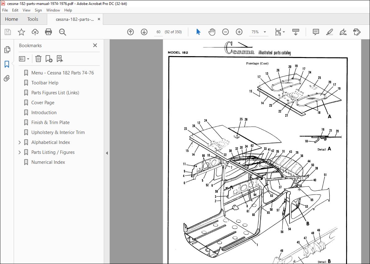
17. Fuselage Assembly………………………………… 76
18. Fuselage Front Section Assembly……………………. 78
19. Front Doorpost Bulkhead Assembly…………………… 82
20. Console Structure Assembly………………………… 84
21. Front Section Tunnel Components……………………. 86
22. Firewall Assembly………………………………… 88
23. Firewall Grommets Installation…………………….. 90
24. Center Cabin Section Assembly …………………….. 92
25. Rear Doorpost Bulkhead Assembly……………………. 96
26. Lower Cabin Section Assembly………………………. 98
27. Landing Gear Bulkhead Assembly……………………..102
28. Windshield Installation……………………………104
29. Aft Cabin Windows Installation……………………..106
30. Tailcone Assembly – Extended Baggage Compartment……..108
31. Battery Box Installation…………………………..112
32. Aft Tailcone Assembly Sta. 209.000 to 230.187………..114
33. Stinger Installation………………………………116
34. Nose Gear Installation…………………………….118
35. Nose Gear Steering System Installation………………122
36. Nose Gear Shock Strut Assembly……………………..124
37. Cleveland Nose Wheel Assembly………………………126
38. Nose Gear Wheel Assembly – Alternate………………..127
39. Shimmy Dampener Assembly…………………………..128
40. Main Landing Gear Installation……………………..130
40A. Main Landing Gear Installation…………………….132
41. Main Wheel & Brake Assembly………………………..136
42. Main Landing Gear Wheel & Brake Assembly (Alternate)….138
43. Left Cabin Door Assembly…………………………..140
44. Right Cabin Door Assembly………………………….144
44A. Right Cabin Door Assembly – Openable Window…………146
45. Cabin Door Latch Assembly………………………….150
46. Baggage Door Installation………………………….152
47. Cabin Top & Firewall Upholstery Installation…………154
48. Cabin Door Upholstery Installation………………….158
49. Upholstery Cabin Side & Floorboard Installation………160
50. Fuselage Soundproofing Installation…………………164
51. Pilot & Co-Pilot Seat Installation – Standard………..166
52. Infinite Adjust Front Seat Installation……………..170
52A. Infinite Adjust Front Seat Installation…………….174
53. Rear Seat Assembly………………………………..180
54. Auxiliary Seat Installation………………………..182
55. Instrument Panel Equipment Installation……………..184
55A. Instrument Panel Equipment Installation…………….190
55B. Stationary Instrument Panel Structure Assembly………194
56. Post Lighted Instrument Panel Installation…………..198
57. Map Compartment Installation……………………….200
58. Fuselage Equipment Installation…………………….202
59. Portable Stretcher Installation…………………….205
60. Rear View Mirror & Compass Installation……………..206
61. Propeller Installation…………………………….208
62. Propeller Installation…………………………….210
63. Engine Cowl Assembly………………………………212
64. Engine Installation……………………………….216
65. Engine Assembly…………………………………..218
66. Engine Components (not illustrated)…………………221
67. Propeller Governor Assembly – Alternate……………..222
68. Engine Exhaust Assembly……………………………224
68A. Engine Exhaust Assembly…………………………..225
69. Engine Baffles Installation………………………..226
70. Cowl Flaps Control System Installation………………230
71. Winterization Equipment Installation………………..232
72. Cabin Ventilation System…………………………..234
72A. Cabin Ventilation System………………………….238
73. Cabin Heating & Defrosting System…………………..240
74. Brake System Installation………………………….242
75. Brake & Rudder Pedals Installation………………….246
76. Master Brake Cylinder Assembly……………………..248
77. Control Column Installation………………………..250
78. Control Wheel & Switches Installation……………….252
78A. Control Wheel & Switches Installation………………254
79. Console Installation………………………………256
80. Aileron Controls Installation………………………260
81. Elevator Control System……………………………262
82. Elevator Trim Control System……………………….264
82A. Elevator Electric Trim Components Installation………266
82B. Elevator Trim Tab Actuator Assembly………………..269
83. Electric Flap System Installation…………………..270
84. Flap Control Detail Installation……………………274
85. Rudder Control System Installation………………….276
86. Pitot System Installation………………………….278
86A. Encoding Altimeter Installation……………………282
87. Fuel System Installation…………………………..284
88. Fuel Strainer & Drain Control Installation…………..286
89. Fuel Primer System Installation…………………….288
90. Oil System Installation……………………………290
91. Vacuum System Installation…………………………292
92. Oxygen System Installation…………………………296
92A. Oxygen System Installation………………………..300
93. Electrical Equipment Installation…………………..304
94. Instrument Panel Lights Installation………………..306
95. Instrument Panel Light & Console Installation………..308
96. Flashing Beacon Light Installation………………….310
97. Courtesy Light Installation………………………..312
98. Shock Mounted Alternator Installation……………….313
99. Seat Belt & Shoulder Harness Installation……………314
100. Console Cover & Lighting Installation………………316
101. Inertia Reel Installation…………………………318
Numerical Index………………………………………….321
PLEASE NOTE:
- This is the same manual used by the dealers to diagnose and troubleshoot your vehicle
- You will be directed to the download page as soon as the purchase is completed. The whole payment and downloading process will take anywhere between 2-5 minutes
- Need any other service / repair / parts manual, please feel free to contact [email protected] . We still have 50,000 manuals unlisted
S.V


