1948-1957 Harley Davidson Service Manual – PDF DOWNLOAD
DESCRIPTION:
1948-1957 Harley Davidson Service Manual – PDF DOWNLOAD
- Red light marked “G.EN” in center of instrument panel indicates whether or not generator is charging. Red light marked “OIL” in center of instrument panel indicates whether or not oil is circulating. All Models: When switch is turned “ON” preparatory to starting engine, both lights should go “ON.” (Exception: When switch is turned “ON” immediately after engine has been primed by cranking. oil pressure signal may not light, but will light after a few seconds. This is due to oil pressure built up by cranking and is most likely to be noticed in cold weather.) With engine started and running at a fair idling speed, both lights should go “OFF.
- ” At slow idling speed or under about 20 miles per hour road speed in high gear, generator signal will normally flash “ON” and “OFF” because at that speed generator output is very low and unsteady. Should generator signal fail to go “OFF” at speeds above approximately 20 miles per hour. generator is either not charging at all or its output is not up to normal and it should be inspected at once. Should oil circulation signal fail to go “OFF”, at speeds above idling, it is most likely due to: empty oil tank; oil supply badly diluted, or using very light grade of oil and pump not building up normal pressure; if freezing weather, oil feed pipe may be clogged with ice or sludge.
- However, it may be: grounded oil signal switch wire, faulty signal switch; or oil pump in bad order. Give due attention to oil supply and, if signal still does not operate normally, check to see if oil returns to tank. To do this, remove oil tank cap and, with engine running, look for pulsating return of oil. A small flashlight is an aid in making this check. If oil is returning, motorcycle can be driven slowly, but no further than absolutely necessary before checking and servicing oiling system. If oil is not returning, do not drive further before having the fault corrected, as engine is likely to be damaged.
All Models: Starting Cold Engine: Set choke lever in fully-closed position, open throttle wide, and with ignition switch “OFF,” prime cylinders by operating starter crank once or twice. Then, with choke lever set ¼ or ½ closed in mild weather,¾ or fully closed in extremely cold weather, and throttle slightly open, turn ignition switch “ON” and start engine with vigorous strokes of starter.
CAUTION:
- It is only in cold weather that engine may start best with choke fully closed, and even then, it will have to be moved from this position immediately after engine starts. Under no conditions will engine continue to run with full choke. As soon as engine starts, set throttle for moderate idling speed while warming up or until ready to set motorcycle in motion. As engine warms up and misfires due to an mixture, gradually move choke lever toward open position. After engine has thoroughly warmed up, move choke lever to fully open position. Starting Warm Engine:
- This applies to engine half way between hot and cold. Move choke lever to 1/_. closed position and with throttle closed, operate starter once or twice. Then, with throttle ¼ to ~13 open, turn ignition switch “ON” and operate starter. Soon after engine starts, choke lever should be moved back to fully open position. Remember: This procedure calls for having throttle part way open during starting strokes after switch has been turned “ON.
- ” Starting Hot Engine: If engine has been shut off for only a brief period and is at about normal running temperature, it is not necessary to use choke lever. Simply close throttle, turn ignition switch “ON” and operate starter. With some engines, depending on -r adjustment, hot starting is more dependable if starter is given one stroke before turning ignition switch “ON.” When a hot engine does not start readily, that is, with two or three starter strokes, it is usually due to an -over-rich (flooded) condition, and the proper procedure then is to open throttle wide so more air can enter, closing it quickly as engine starts.
TO STOP ENGINE
Stop engine by turning ignition switch “OFF.” If engine should be stalled or stopped in any other way than with switch, tum switch “OFF” at once to prevent battery from being discharged through circuit breaker points. Don’t idle engine unnecessarily with motorcycle standing.
RUNNING IN NEW ENGINE
Don’t run new motorcycle faster than 35 miles per hour the first 250 miles; 40 miles per hour the second 250 miles; 45 miles per hour (sidecar) or 50 miles per hour (solo) the next SOO miles. A void running at or near top speed for lon(J distances below 2000 miles.
INSTRUMENT PANEL SIGNAL LIGHTS
TABLE OF CONTENTS:
1948-1957 Harley Davidson Service Manual – PDF DOWNLOAD
Product
General Specifications 1948-1954 4
General Specifications 1955-1957 6
Lubrication Chart 8
Signal Lights 9
Starting Engine 9
Stopping Engine 9
Running in New Engine 9
High Speed Tips 10
Trouble Shooting Charts 10
engine 10
generator 11
carburetor 11
transmission 11
brakes 12
General Lubrication 12
Lubrication Chart 13
Servicing Air Cleaner 14
Initial Servicing of New Motorcycle 14
first 250 miles 14
first 750 miles 14
first 1500 miles 15
Regular Interval Inspection &
Maintenance 15
Care & Lubrication of Drive Chain 16
adjusting drive chain 16
adjusting front chain 16
adjusting rear chain 16
lubrication front chain 16
lubrication rear chain 17
repairing drive chain 17
Clutch & gear shifter 18
Compensating sprocket (early style) 18
Chassis
Wheels 20
general 20
removal 20
removal (side car) 21
servicing wheel hubs 22
replacing rear wheel sprocket 23
spoking wheels 23
truing wheels 24
removing & installing tires 25
Shop Data
2
wheels 26
Servicing Handlebar Controls 28
early model 28
late model 29
Removing & lnstalllng Forks 29
springers , 31
Fork Frame & Handlebar Alignment 34
rough check for fork alignment 34
rough check for frame alignment 34
frame alignment diagram 35
springer shock 36
Glide Forks 37
general 37
changing oil 37
glide fork diagram 39
glide fork diagram (adjustable) 40
disassembling fork sliders & tubes 41
adjusting steering damper 41
adjusting fork trail (adjustable) 42
disassembling front fork 42
steering head bearings 43
replacing slider bushings 43
inspecting & servicing fork 44
straightening fork tubes 44
straightening fork stem & bracket
assembly 45
assembling fork 46
assembling fork (adjustable) 47
Brakes 48
disassemble front brake (glide) 48
inspection & servicing (glide) 48
assembling front brake (glide) 48
adjusting front brake cable (glide) 48
adjusting front brake shoes (glide) 48
glide brake diagram 49
springer brake diagram 49
rear brake diagram 50
adjusting rear & springer brakes 51
servicing rear & springer brakes 51
Servicing Saddle Spring Post 52
Engines
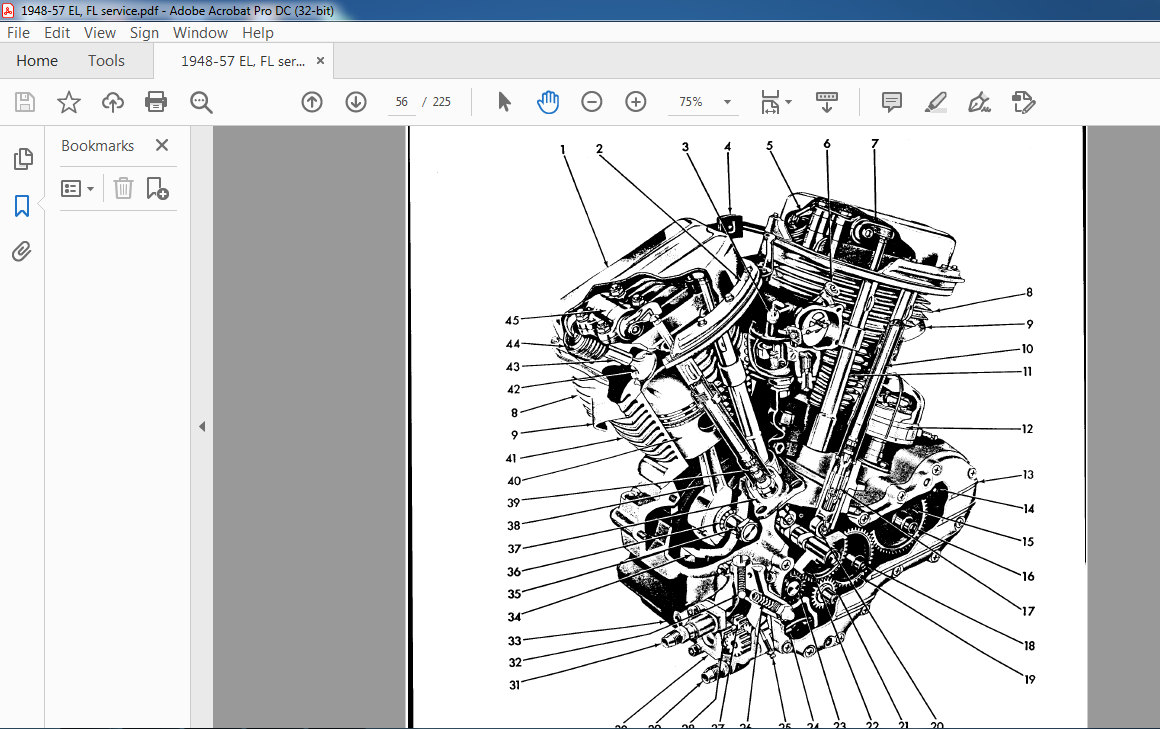
general 54
engine diagram 55
lubrication 56
winter lubrication · 57
changing oil 57
oil pressure signallight 57
operating oil pressure 57
oil filter 57
pressure oil system 58
return oil system 59
engine repair procedure 59
pressure oil system diagram 61
return oil system (early) 62
return oil system (late) 63
disassembling cylinder & piston 64
refinishing cylinders 65
fitting piston rings 66
connecting rod bushings 67
straightening connecting rods 68
assembling cylinder & piston 69
Shop Data
cylinder reboring & piston fitting 70
pistons & rocker arms 72
removing cylinder head assembly 73
disassembling cylinder head 73
replacing valve guides 73
cylinder head diagram 74
replacing valve seats 75
grinding valve faces & seats 75
lapping valve faces & seats 76
assembling cylinder head 76
adjusting tappets 76
Shop Data
valve guides 77
installing high lift cam 78
intake valve guides 79
valve guide sizes 80
exhaust valve rotating mechanism 81
valve spring testing information 82
FLH valve springs 83
hydraulic pushrods 84
adjusting hydraulic pushrods 85
servicing hydraulic pushrods 86
tappet che-::k valve servicing 88
misc clearances & oil pressure 89
Oil Pump 90
servicing oil pump 90
installing oil pump 91
Shop Data
oil control 92
oil pump charges 94
late oil pump 96
oil pump flow diagram 97
1948-1954 Lower End Diagram 98
Disassembling Lower End 99
installing timing gears 100
installing timing gear case cover 100
1948-1954 gear & crankcase data
procedures 100
truing & sizing main bearing
races 101
fitting main bearings 102
servicing flywheels & installing
crankpan 102
truing & sizing connecting rod
lower races 102
determining correct lower
bearing fit 103
assembling connecting rods &
flywheels 103
truing flywheels 104
assembling crankcases 105
installing generator 106
Shop Data
removing & replacing pinion
shaft gear 1 p7
crankcase drilling procedures 109
connecting rod roller & retainer
size chart 111
engine fitting specifications 112
servicing pinion shaft rollers 113
pinion shaft assembly diagram 114
1955-1957 oil pump diagram 115
1953-1957 Valve Tappets & Guides 116
1954-1957 Gear Case Diagram 118
1954-1957 Gear Case Timing Cases 119
1955-1957 Crankcase 122
1955-1957 Complete Lower End
Procedures 122-130
Shop Data
engine fitting data ’55 & later 131
[4]
roller bearing roller guides 132
identification of roller retainers 134
Adjusting Carburetor 136
disassembling carburetor 136
carburetor diagram 137
cleaning & repairing carburetor 138
assembling carburetor 139
air cleaner 139
fuel strainer 140
fuel tanks 140
Shop Data
servicing notes for carburetor 141
specification chart for carburetor 142
float bowl 143
adjusting carburetor on engine 144
carburetor conversions 145
manifold 146
carburetor specifications 147
general 148
clutch general 151
adjusting foot clutch control 151
adjusting hand clutch control 151
adjusting clutch 152
disassembling clutch 152
cleaning & inspecting clutch 153
assembling clutch 154
disassembling starter 155
cleaning & inspecting starter 155
assembling starter 155
disassembling starter clutch 155
cleaning & inspecting starter
clutch 155
assembling starter clutch 156
starter diagram 156
adjusting shifting linkage __ 157
adjusting foot shifter cover 157
replacing main drive gear oil
seal 157
removing shifter cover 158
disassembling shifter cover 159
cleaning & inspection shifter
cover 159
assembling shifter cover 159
shifter cover diagram
(footshift) 160
replacing shifter cover 162
removing shifter forks 162
disassembling shifter forks 162
cleaning & inspection shifter
forks : 162
assembling shifter forks 163
disassembling gear box 163
counter shaft assembly diagram 164
disassembling mainshaft 165
disassembling main drive gear 166
assembling main drive gear 167
assemtljing main shaft 167
assembling counter shaft 167
transmission vent screw 168
Electrical
wiring diagram for 1948 model 170
wiring diagram for 1949-54 171
wiring diagram for 1955-57
(standard) 172
wiring diagram for 1955-57
(radio special) 173
Ignition Light Switch 176
Button Switch 1n
Headlamp Dimmer & Horn Switch 177
Headlamps 178
3 Brush 32E Generator Diagram 179
radio 2 brush generator diagram 181
trouble shooting & repairing
generator 183
removing generator 184
testing field coils & brush holders
assembled 184
disassembling generator 186
testing armature 188
turning down commutator 189
undercutting commutator 189
reassembling generator 189
assembling generator to engine 190
generator charging rate 190
replacing generator brushes 190
cleaning commutator 190
lubricating commutator end
armature bearing 191
cut out relay 191
generator brush diagram 192
current & voltage regulator 193
fan cooled generator , 194
fan cooled generator diagram 195
Shop Data
fan cooled gener ator 198
model 32E 2R radio generator
diagram 199
model 48 3 brush fan cooled
generator diagram , 200
model 48 2 brush fan cooled
generator diagram 201
model 51 52 & later 2 brush fan
cooled generator diagram 202
model 32E standard 3 brush
generator diagram , 203
model 52 standard 3 brush
generator diagram 204
Circuit Breaker Description 205
single contact point manual
advance 205
double contact point manual
advance 205
adjusting circuit breaker points 206
ch~c~ing & adjusting ignition
timing 206
circ uit breaker diagram 208
removing circuit breaker 21 0
inspection & replacement of
parts circuit breaker 21 0
Ignition Coil 212
Spark Plugs 213
Shop Data
regulator service information 215
Battery 217
Horn 218
Miscellaneous
removing side car from
motorcycle 222
attaching side car to
motorcycle 222
side car wiring digram 222
Servicing Speedometer 223
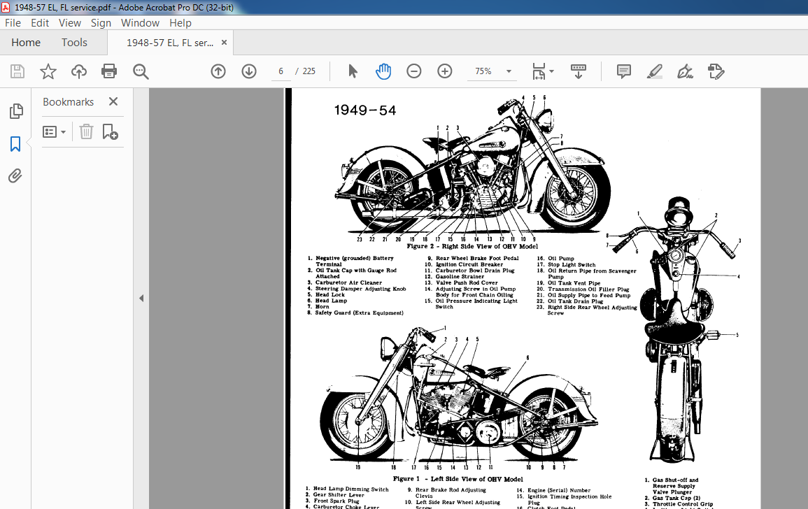
1 Hydraulic Shock Absorber
2 Headlamp Dimming Switch
3 Gear Shifter Lever
4 Front Spark Plug
5, Carburetor Choke Lever
6 Rear Spark Plug
7 Positive Battery Terminal
8 Brake Sleeve Nut
18 11 16 15 14 13 12 11 10 9 8
1948 Left Side View of OHV Model
9 Rear Axle Nut
10 Rear Brake Rod Adjusting Clevis
11 Left Side Rear Wheel Adjusting
Screw
12 Clutch Inspection-Hole Cover
13 Clutch Footpedal Rod
14 Front Chain Inspection-Hole
Cover
15 Engine (Serial) Number
16 Ignition Timing Inspection-
Hole Plug
17 Clutch Footpedal
18 Gear Shifter Rod
19 Front Wheel Axle Nut
20 Front Wheel Brake
Adjusting Sleeve
DIMENSIONS
Wheel Base 60 in
Overall Length 92 in
Overall Width 35 in
CAPACITIES
Fuel Tanks 3-3/4 Gallons (U S )
Oil Tank 1 Gallon (U S )
Transmission 1-1/2 Pints
ENGINE
Model Designation Letters FL – FLH
Number of Cylinders 2
Type 45 Degree V Type
Horsepower FLH 60 0 HP at 5,400 R P M
FL 55 0 HP at 5,400 R P M
Taxable Horsepower 9 44
Bore (87 3mm) 3-7/16 in
Stroke (100 8mm) 3-31/32 in
Piston Displacement (1,207 cc) 73 66 cu in
Torque FLH 65 lb-ft at 3,200 R P M
_ FL 62 lb-ft at 3,200 R P M
Compression Ratio FLH 8 to 1
FL 7 25 to 1
Spark Plug (Heat range for average usei No 3-4
NOTE: The engine (serial) number is stamped
on the left side of the engine crankcase Always
give this number when ordering parts or
ma king an inquiry
TRANSMISSION
Type Constant Mesh
Speeds – Foot Shift 4 Forward
Hand Shift , 4 Forward
(Optional) 3 Forward and 1 Reverse
VIDEO PREVIEW OF THE MANUAL:
IMAGES PREVIEW OF THE MANUAL:
PLEASE NOTE:
- This is the SAME MANUAL used by the dealerships to diagnose your vehicle
- No waiting for couriers / posts as this is a PDF manual and you can download it within 2 minutes time once you make the payment.
- Your payment is all safe and the delivery of the manual is INSTANT – You will be taken to the DOWNLOAD PAGE.
- So have no hesitations whatsoever and write to us about any queries you may have : heydownloadss @gmail.com
S.M